Acura RL (1996-2004 year). Manual — part 379
(From page
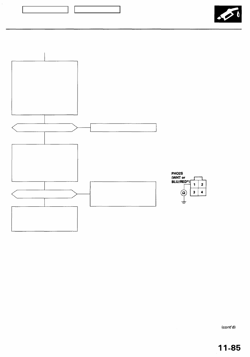
Check for a short in the HO2S:
1. Turn the ignition switch OFF.
2. Disconnect the right primary
HO2S (Bank 1, Sensor 1) or
left primary HO2S* (Bank 2,
Sensor 1) connector.
3. Start the engine and let it idle.
4. Check the right primary HO2S
(Bank 1, Sensor 1) or left pri-
mary HO2S* (Bank 2, Sensor
1) output voltage with the
scan tool.
Does it stay at 0.5 V or less?
YES
Check for a short in the wires:
1. Turn the ignition switch OFF.
2. Disconnect the PCM connec-
tor D (22P).
3. Check for continuity between
No. 1 terminal on the harness
side of the HO2S connector
and body ground.
Replace the HO2S.
Is there continuity?
NO
Substitute a known-good PCM
and recheck (see page
for
immobilizer information). If symp-
tom/indication goes away, replace
the original PCM.
Repair short in the wire between
PCM (D19 or D18*) and right pri-
mary HO2S (Bank 1, Sensor 1) or
left primary HO2S* (Bank 2,
Sensor 1).
RIGHT PRIMARY HO2S (Bank 1, Sensor 1) CONNECTOR (C119)
or LEFT PRIMARY HO2S (Bank 1, Sensor 1) CONNECTOR (C126)
Wire side of female terminals
*: P0151
YES
NO
Main Menu
Table of Contents
PGM-FI System
Primary Heated Oxygen Sensor (HO2S) (Sensor 1) (cont'd)
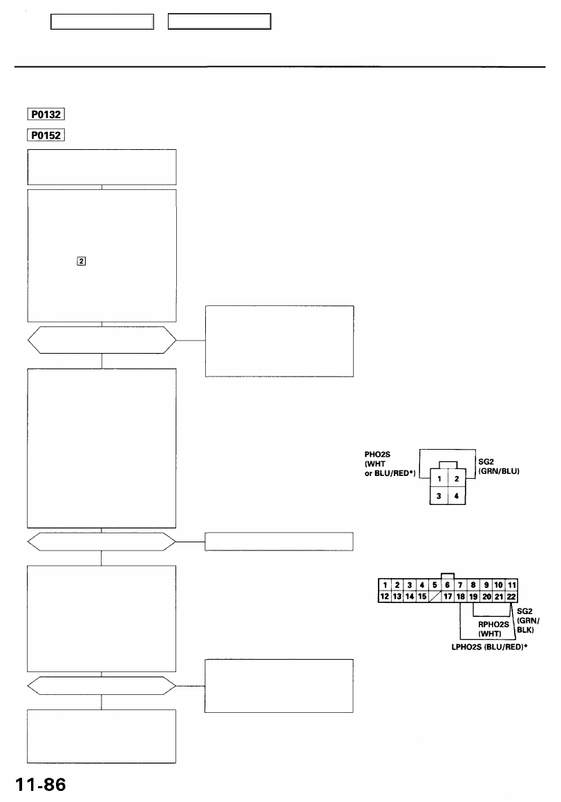
The scan tool indicates Diagnostic Trouble Code (DTC) P0132: A high voltage problem in the Right Primary
Heated Oxygen Sensor (Right Primary HO2S) (Bank 1, Sensor 1) circuit.
The scan tool indicates Diagnostic Trouble Code (DTC) P0152: A high voltage problem in the Left Primary
Heated Oxygen Sensor (Left Primary HO2S) (Bank 2, Sensor 1) circuit.
— The MIL has been reported on.
— DTC P0132 and/or P0152 are
stored.
Problem verification:
1. Do the PCM Reset Procedure.
2. Start the engine. Hold the engine
at 3,000 rpm with no load (in
Park or neutral) until the radia-
torfancomeson.
3. Test-drive with the transmis-
sion in position.
4. Check the right primary HO2S
(Bank 1, Sensor 1) or left primary
HO2S* (Bank 2, Sensor 1) out-
put voltage with the scan tool
during deceleration using com-
pletely closed throttle.
Does the voltage stay at 0.9 V
or more?
YES
Check for an open in the HO2S:
1. Turn the ignition switch OFF.
2. Disconnect the right primary
HO2S (Bank 1, Sensor 1) or left
primary HO2S* (Bank 2, Sen-
sor 1 (connector.
3. Install a jumper wire on the
harness side of the right primary
HO2S (Bank 1, Sensor 1) or left
primary HO2S* connector
between terminals No. 1 and
No. 2.
4. Turn the ignition switch ON (II).
5. Check the right primary HO2S
(Bank 1, Sensor 1) or left pri-
mary HO2S* (Bank 2, Sensor 1)
output voltage with the scan tool.
Is there 0.9 V or more?
YES
Check for an open in the wires
(PO2S line):
1. Turn the ignition switch OFF.
2. Install a jumper wire on the
PCM connector between D19,
or D18* and D22.
3. Turn the ignition switch ON (II).
4. Check the right primary HO2S
(Bank 1, Sensor 1) or left pri-
mary HO2S* (Bank 2, Sensor 1)
output voltage with the scan tool.
Is there 0.9 V or more?
YES
Substitute a known-good PCM and
recheck (see page
for immo-
bilizer information). If symp-
tom/indication goes away, replace
the original PCM.
NO
Intermittent failure, system is OK
at this time. Check for poor con-
nections or loose wires at C251,
C254 (located at left shock tower),
C119 (right primary HO2S (Bank 1,
Sensor 1)) or C126 (left primary
HO2S (Bank 2, Sensor 1))*
RIGHT PRIMARY HO2S (Bank 1, Sensor 1) CONNECTOR (C119)
or LEFT PRIMARY HO2S (Bank 2, Sensor 1) CONNECTOR (C126)
JUMPER WIRE
Replace the HO2S.
Wire side of female terminals
PCM CONNECTOR D (22P)
Repair open in the wire between
PCM (D19 or D18*) and right pri-
mary HO2S (Bank 1, Sensor 1) or
left primary HO2S* (Bank 2,
Sensor 1).
Wire side of female terminals
*: P0152
NO
NO
JUMPER
WIRE
Main Menu
Table of Contents
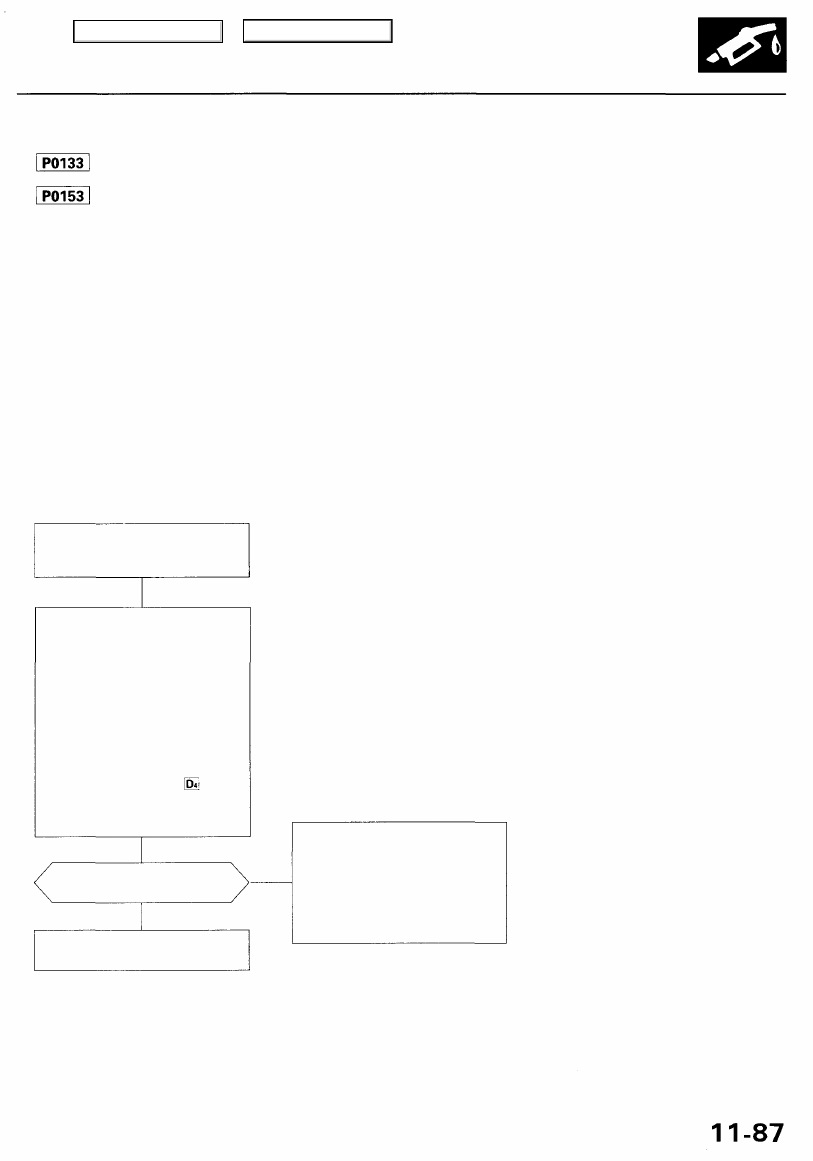
The scan tool indicates Diagnostic Trouble Code (DTC) P0133: A slow response problem in the Right Primary
Heated Oxygen Sensor (Right Primary HO2S) (Bank 1, Sensor 1) circuit.
The scan tool indicates Diagnostic Trouble Code (DTC) P0153: A slow response problem in the Left Primary
Heated Oxygen Sensor (Left Primary HO2S) (Bank 2, Sensor 1) circuit.
Description
By controlling the air/fuel ratio with a Primary HO2S (Sensor 1) and a Secondary HO2S (Sensor 2), the deterioration of the
Primary HO2S (Sensor 1) can be evaluated by its feedback period. When the feedback period of the HO2S exceeds a certain
value during stable driving conditions, the sensor will be judged as deteriorated. When deterioration has been detected dur-
ing two consecutive trips, the MIL comes on and DTC P0133 or P0153 will be stored.
NOTE: If DTC P0131, P0132 and/or P0135 are stored at the same time as DTC P0133, troubleshoot those DTCs first, then
troubleshoot DTC P0133. If DTC P0151, P0152 and/or P0155 are stored at the same time as DTC P0153, troubleshoot those
DTCs first, then troubleshoot DTC P0153.
Is DTC P0133 and/or P0153
indicated?
YES
Replace the primary HO2S (Sen-
sor 1).
NO
Intermittent failure, system is OK
at this time. Check for poor con-
nections or loose wires at C251,
C254 (located at left shock tower),
C119 (right primary HO2S (Bank 1,
Sensor 1)) or C126 (left primary
HO2S (Bank 2, Sensor 1))* and
PCM.
*: P0153
Problem verification:
1. Do the PCM Reset Procedure.
2. Start the engine. Hold the
engine at 3,000 rpm with no
load (in Park or neutral) until
the radiator fan comes on.
3. Connect the SCS service con-
nector.
4. Test-drive under following
conditions.
— 55 mph (88 km/h) steady
speed
— Transmission in posi-
tion
— Until readiness code comes
on
Possible Cause
• Primary HO2S (Sensor 1) Deterioration
• Primary HO2S Heater (Sensor 1) Deterioration
• Exhaust system leakage
Troubleshooting Flowchart
— The MIL has been reported on.
— DTC P0133 and/or P0153
stored.
Main Menu
Table of Contents
PGM-FI System
Secondary Heated Oxygen Sensor (HO2S) (Sensor 2)
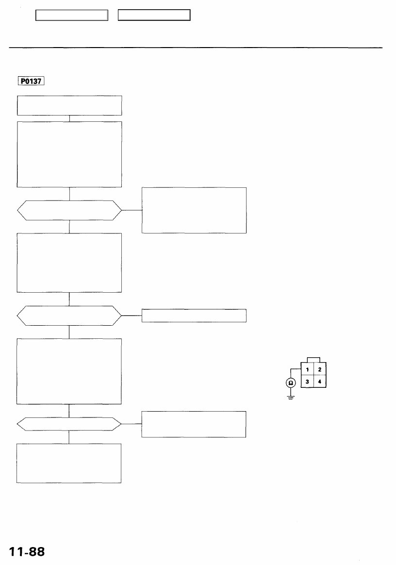
The scan tool indicates Diagnostic Trouble Code (DTC) P0137: A low voltage problem in the Secondary Heated
Oxygen Sensor (Secondary HO2S) (Sensor 2) circuit.
— The MIL has been reported on.
— DTC P0137 is stored.
Problem verification:
1. Do the PCM Reset Procedure.
2. Start the engine. Hold the
engine at 3,000 rpm with no
load (in Park or neutral) until
the radiator fan comes on.
3. Check the secondary HO2S
(Sensor 2) output voltage with
the scan tool at 3,000 rpm.
Does the voltage stay at 0.3 V
or less?
YES
Check for a short in the HO2S:
1. Turn the ignition switch OFF.
2. Disconnect the secondary
HO2S (Sensor 2) connector.
3. Start the engine.
4. Check the secondary HO2S
(Sensor 2) output with the scan
tool.
Does the voltage stay at 0.3 V
or less?
YES
Check for a short in the wire
(SO2S line):
1. Turn the ignition switch OFF.
2. Disconnect the PCM connec-
tor F (8P).
3. Check for continuity between
No. 1 terminal on the second-
ary HO2S (Sensor 2) connec-
tor and body ground.
Is there continuity?
NO
Substitute a known-good PCM
and recheck (see page
for
immobilizer information). If symp-
tom/indication goes away, replace
the original PCM.
NO
Intermittent failure, system is OK
at this time. Check for poor con-
nections or loose wires at C444
(located behind right kick panel),
C610 (secondary HO2S (Sensor
2)) and PCM.
Replace the HO2S (Sensor 2).
SECONDARY
HO2S (Sensor 2) CONNECTOR (C610)
SHO2S
(WHT/
RED)
Repair short in the wire between
PCM (F2) and secondary HO2S
(Sensor 2).
Wire side of female terminals
YES
NO
Main Menu
Table of Contents
Нет комментариевНе стесняйтесь поделиться с нами вашим ценным мнением.
Текст