Acura RL (1996-2004 year). Manual — part 600
A/C System
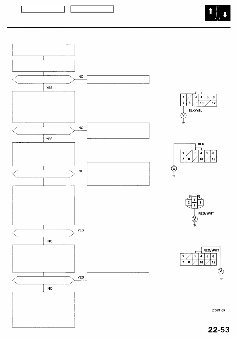
Both fans and compressor do not
work at all.
Check the No. 3 (7.5 A) fuse in
the under-dash fuse/relay box.
Is the fuse OK?
Check for an open in the wire:
1. Disconnect the fan control
unit 12P connector.
2. Turn the ignition switch ON (II).
3. Measure the voltage between
the No. 7 terminal and body
ground.
Is there battery voltage?
Check for an open in the wire:
1. Turn the ignition switch OFF.
2. Check for continuity between
the No. 3 terminal of the fan
control unit and body ground.
Is there continuity?
YES
Check for an open in the wire:
1. Reconnect the fan control unit
12P connector.
2. Disconnect the A/C pressure
switch 4P connector.
3. Turn the ignition switch ON (II).
4. Measure the voltage between
the No. 4 terminal and body
ground.
Is there battery voltage?
Check the fan control unit:
Measure the voltage between the
No. 4 terminal of the fan control
unit 12P c o n n e c t o r and body
ground with the fan control unit
12P connector connected.
Is there battery voltage?
Check for loose wires or poor
connections at the fan control
unit 12P connector. If the con-
nections are good, substitute a
known-good fan control unit,
and recheck. If the symptom/
indication goes away, replace
the original fan control unit.
Replace the fuse, and recheck.
FAN CONTROL UNIT 12P CONNECTOR
Repair open in the wire between
the No. 3 fuse and the fan con-
trol unit
Wire side of female terminals
Check for an open in the wire
between the fan control unit and
body ground. If the wire is OK,
check for poor ground at G401
and G402.
A/C PRESSURE SWITCH 4P CONNECTOR
Wire side of female terminals
Repair open in the wire between
the A/C pressure switch and the
fan control unit.
Main Menu
Table of Contents
Troubleshooting
A/C System (cont'd)
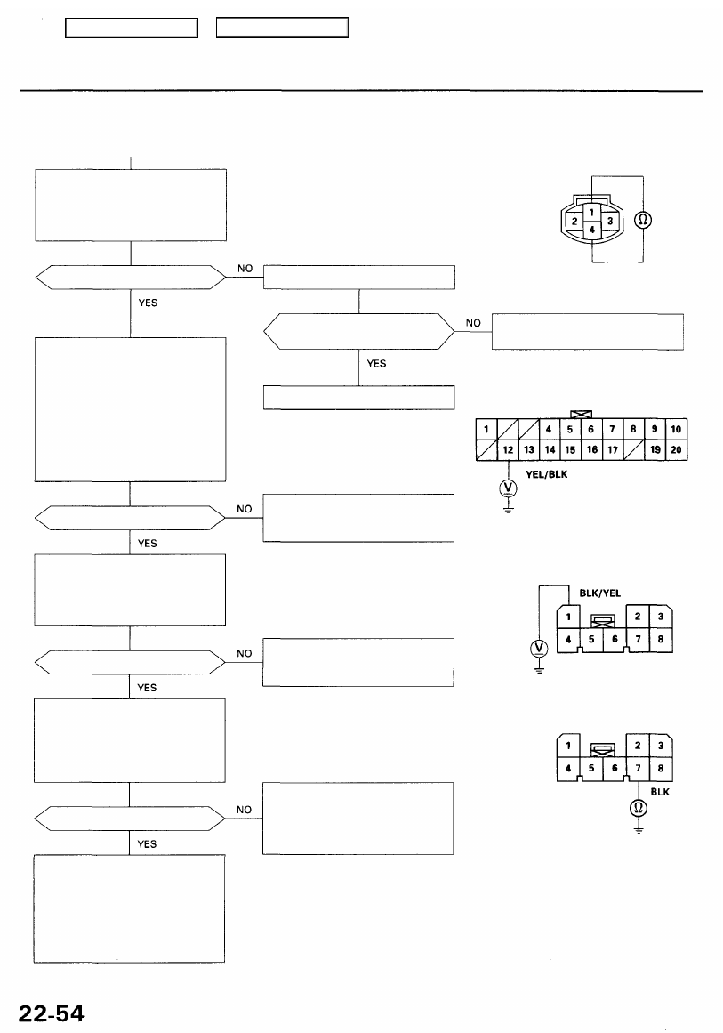
Check the A/C pressure switch:
1. Turn the ignition switch OFF.
2. Check for continuity between
the No. 1 and No. 4 terminals
of the A/C pressure switch.
Is there continuity?
Check for an open in the wire:
1. Reconnect the A/C pressure
switch 4P connector.
2. Remove the climate control
), and dis-
connect the 8P and 20P con-
nectors.
3. Turn the ignition switch ON (II).
4. Measure the voltage between
the No. 12 terminal of the 20P
connector and body ground.
Is there battery voltage?
Check for an open in the wire:
Measure the voltage between the
No. 1 terminal of the climate con-
trol unit 8P connector and body
ground.
Is there battery voltage?
Check for an open in the wire:
1. Turn the ignition switch OFF.
2. Check for continuity between
the No. 7 terminal of the cli-
mate control unit 8P connec-
tor and body ground
Is there continuity?
Check for loose wires or poor con-
nections at the climate control
unit 8P and 20P connectors. If the
connections are good, substitute a
known-good climate control unit,
and recheck. If the symptom/indi-
cation goes away, replace the
original climate control unit.
A/C PRESSURE SWITCH
Is the pressure within specifi-
cations?
Repair the A/C pressure prob-
lem.
CLIMATE CONTROL UNIT 20P CONNECTOR
Repair open in the wire between
the A/C pressure switch and the
climate control unit.
Wire side of female terminals
CLIMATE CONTROL UNIT 8P CONNECTOR
Repair open in the wire between
the No. 3 fuse and the climate
control unit.
Wire side of female terminals
Check for an open in the wire
between the climate control unit
and body ground. If the wire is
OK, check for poor ground at
G401 and G402.
Replace the A/C pressure switch.
Check for A/C system pressure.
Main Menu
Table of Contents
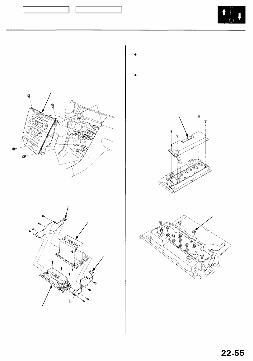
Climate Control Unit
Replacement Bulb Replacement
1. Remove the center air vent and center console trim
(see
).
2. Remove the bolts and the climate control unit
together with audio unit, then disconnect the con-
nectors.
CLIMATE CONTROL UNIT
3. Remove the bolts, the screws and the brackets, then
remove the screws and the climate control unit
from the audio unit.
BRACKET
AUDIO UNIT
BRACKET
CAUTION:
Before replacing bulbs, discharge the static electrici-
ty (which accumulated on you when you removed
the climate control unit) by touching the door striker
or other body parts.
Do not touch the electronic components on the
printed circuit board in the climate control unit.
1. Remove the climate control unit (see previous column).
2. Carefully remove the self-tapping screws and the
rear cover.
REAR COVER
3. Remove the bulb(s) with a flat-tip screwdriver.
BULB
4. Install in the reverse order of removal. Make note of
the following items.
NOTE:
• Do not kink or pull on the wires between the con-
trol unit and printed circuit board.
• After installation, operate the climate control unit
to see whether it works properly.
• Run the self-diagnosis function to confirm that
there are no problems in the system.
CLIMATE CONTROL UNIT
4. Install in the reverse order of removal.
Main Menu
Table of Contents
Climate Control Unit
Face Panel/Button Replacement
CAUTION:
Before replacing face panel or buttons, discharge the
static electricity (which accumulated on you when
you removed the climate control unit) by touching
the door striker or other body parts.
Do not touch the electronic components on the
printed circuit board in the climate control unit.
1. Remove the climate control unit (see page
).
2. Remove the temperature control and the fan control
knobs.
TEMPERATURE
CONTROL KNOB
FAN CONTROL
KNOB
3. Carefully remove the self-tapping screws and the
rear cover.
REAR COVER
4. Remove the self-tapping screws, then remove the
clock and the display from the face panel.
DISPLAY
CLOCK
5. If necessary, remove the buttons sequentially from
left to right.
BUTTON
6. Install in the reverse order of removal. Make note of
the following items.
NOTE:
Do not kink or pull on the wires between the con-
trol unit and printed circuit board.
After installation, operate the climate control unit
to see whether it works properly.
Run the self-diagnosis function to confirm that
there are no problems in the system.
FACE PANEL
Main Menu
Table of Contents
Нет комментариевНе стесняйтесь поделиться с нами вашим ценным мнением.
Текст