Acura RL (1996-2004 year). Manual — part 599
Compressor
Compressor clutch does not
engage.
Check the No. 3 (7.5 A) and No. 5
(20 A) fuses in the under-dash fuse/
relay box.
Are the fuses OK?
Remove the compressor clutch
relay from the under-hood relay
box A, and test it (see page
).
Is the relay OK?
Check for an open in the wire:
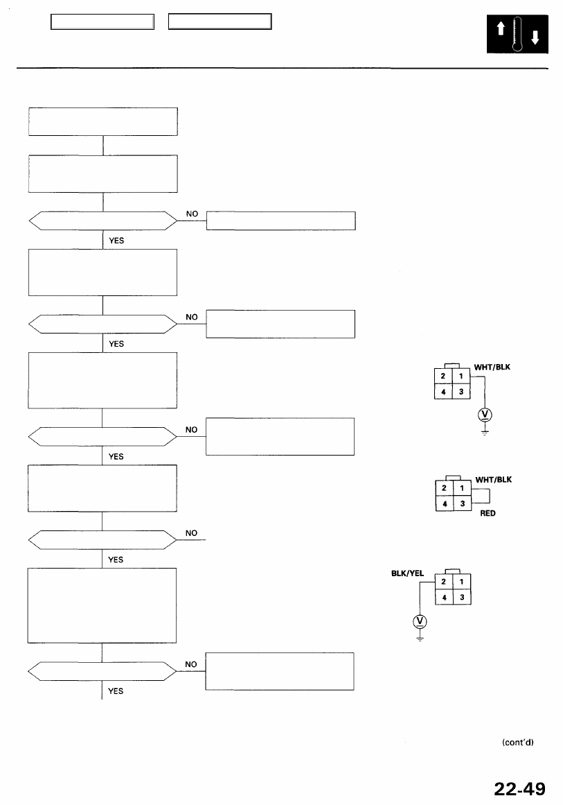
Measure the voltage between the
No. 1 terminal of the compressor
clutch relay 4P socket and body
ground.
Is there battery voltage?
Check the compressor clutch:
Connect the No. 1 and No. 3 termi-
nals of the compressor clutch relay
4P socket with a jumper wire.
Does the compressor clutch click?
Check for an open in the wire:
1. Disconnect the jumper wire.
2. Turn the ignition switch ON (II).
3. Measure the voltage between
the No. 2 terminal of the com-
pressor clutch relay 4P socket
and body ground.
Is there battery voltage?
Replace the fuse(s), and recheck.
Replace the compressor clutch
relay.
COMPRESSOR CLUTCH RELAY
4P SOCKET
Repair open in the wire between
the No. 5 fuse and the compres-
sor clutch relay.
To page
Repair open in the wire between
the No. 3 fuse and the compres-
sor clutch relay.
JUMPER
WIRE
Main Menu
Table of Contents
Troubleshooting
Compressor (cont'd)
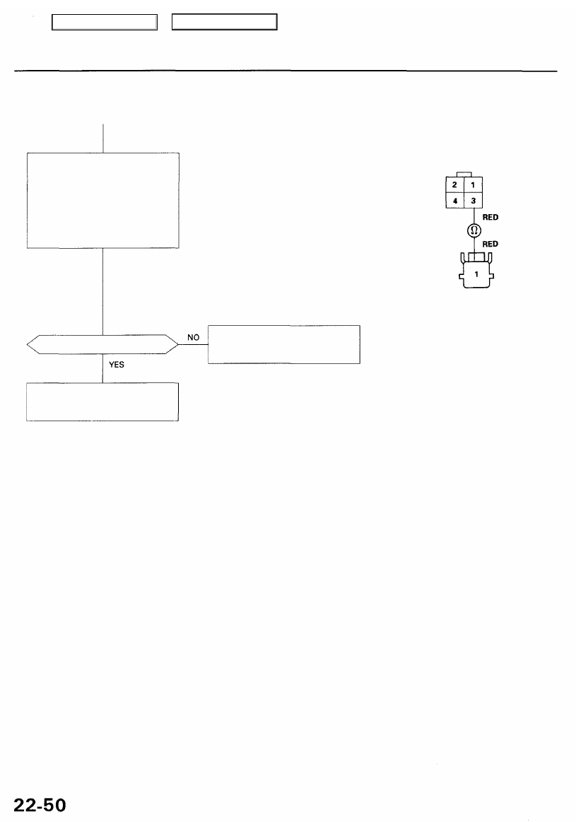
Check for an open in the wire:
1. Disconnect the jumper wire.
2. Disconnect the compressor
clutch 1P connector.
3. Check for continuity between
the No. 3 terminal of the com-
pressor clutch relay 4P socket
and the terminal of the com-
pressor clutch 1P connector.
COMPRESSOR CLUTCH RELAY
4P SOCKET
COMPRESSOR CLUTCH 1P CONNECTOR
Wire side of female terminals
Is there continuity?
Repair open in the wire between
the compressor clutch relay and
the compressor clutch.
Inspect the compressor clutch
clearance and the compressor
clutch field coil (see page
).
Main Menu
Table of Contents
Check the PCM (ACC and ACS
lines):
1. Turn the ignition switch OFF,
then reinstall the compressor
clutch relay.
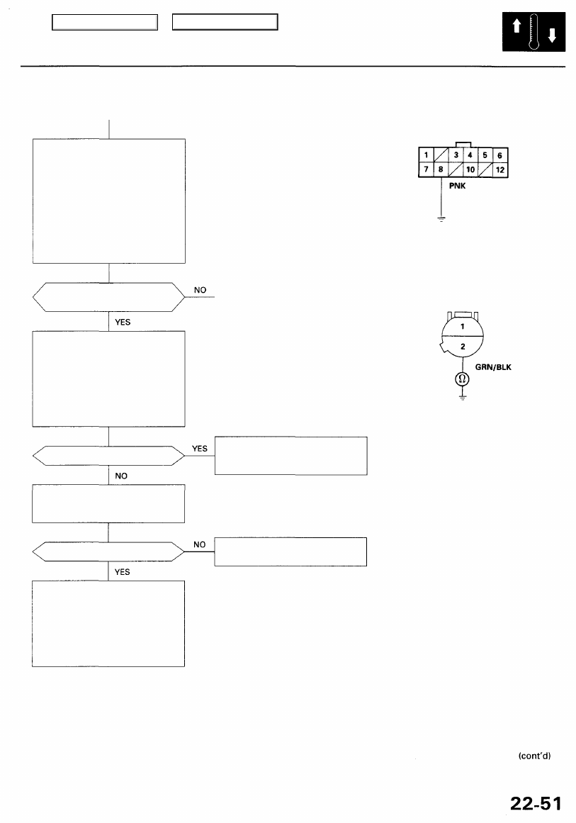
2. Disconnect the fan control
unit 12P connector.
3. Connect the No. 8 terminal and
body ground with a jumper
wire.
4. Turn the ignition switch ON (II),
and start the engine.
Does the compressor clutch
engage?
Is there continuity?
Test the radiator fan control sen-
sor (see Fan Controls in
).
Is the sensor OK?
Check for loose wires or poor
connections at the fan control
unit 12P connector. If the con-
nections are good, substitute a
known-good fan control unit,
and recheck. If the symptom/
indication goes away, replace
original fan control unit.
FAN CONTROL UNIT 12P CONNECTOR
Wire side of female terminals
RADIATOR FAN CONTROL SENSOR 2P CONNECTOR
Wire side of female terminals
Repair short in the wire between
the radiator fan control sensor
and the fan control unit.
Replace the radiator fan control
sensor.
Check for a short in the wire:
1. Turn the ignition switch OFF,
then disconnect the jumper
wire.
2. Disconnect the radiator fan
control sensor 2P connector.
3. Check for continuity between
the No. 2 terminal and body
ground.
JUMPER
WIRE
Main Menu
Table of Contents
Troubleshooting
Compressor (cont'd)
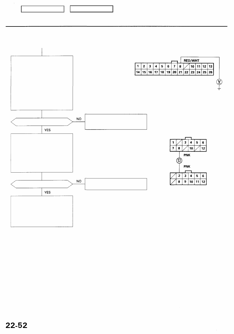
Check for an open in the wire:
1. Turn the ignition switch OFF,
then disconnect the jumper
wire.
2. Make sure the A/C is OFF, then
turn the ignition switch ON (II).
3. Using a *Backprobe Set (T/N
), measure
the voltage between the No. 8
terminal of the PCM connec-
tor A (26P) and body ground
with the PCM connectors con-
nected.
Is there battery voltage?
Is there continuity?
Check for loose wires or poor
connections at the PCM connec-
tor A (26P) and C (12P). If the con-
nections are good, substitute a
known-good PCM, and recheck. If
the symptom/indication goes
away, replace the original PCM.
PCM CONNECTOR A (26P)
Wire side of female terminals
Repair open in the wire between
the compressor clutch relay and
the PCM.
FAN CONTROL UNIT 12P CONNECTOR
Wire side of female terminals
Repair open in the wire between
the fan control unit and the PCM.
PCM CONNECTOR C (12P)
Wire side of female terminals
*How to use the backprobe sets
Connect the backprobe adapters to the stacking patch cords, and connect the cords to a
multimeter. Using the wire insulation as a guide for the contoured tip of the backprobe
adapter, gently slide the tip into the connector from the wire side until it comes in con-
tact with the terminal end of the wire (see
).
Check for an open in the wire:
1. Turn the ignition switch OFF.
2. Disconnect the PCM connec-
tor C (12P).
3. Check for continuity between
the No. 8 terminal of the fan
control unit 12P connector and
the No. 2 terminal of the PCM
connector C (12P).
Main Menu
Table of Contents
Нет комментариевНе стесняйтесь поделиться с нами вашим ценным мнением.
Текст