Acura RL (1996-2004 year). Manual — part 601
Air Mix Control Motor
Replacement
Test
).
2. Remove the glove box back cover and the blower
under cover together with the glove box frame (see
page
).
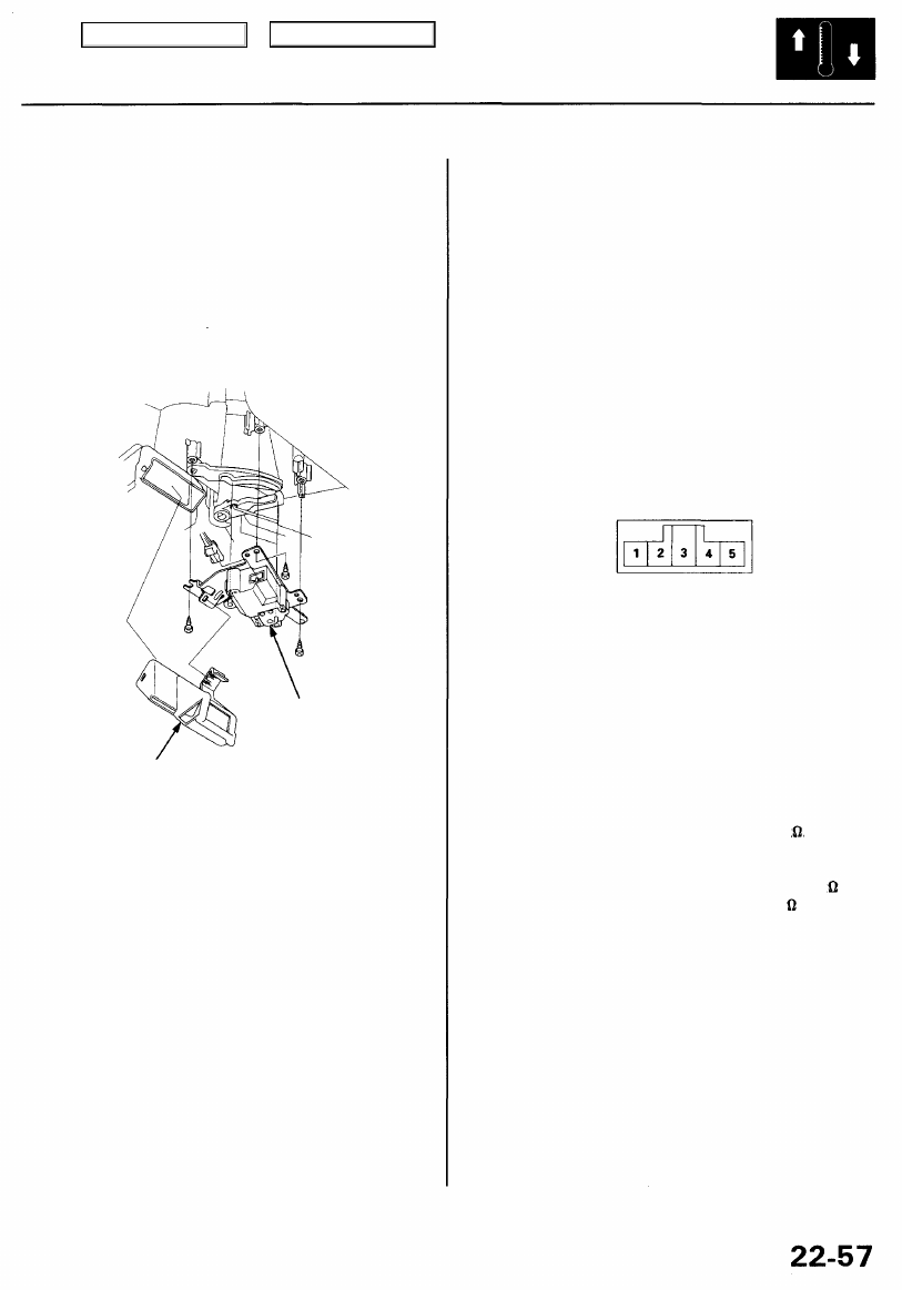
3. Remove the heater outlet from the heater unit.
Disconnect the connector from the air mix control
motor, then remove the self-tapping screws and the
air mix control motor.
AIR MIX
CONTROL
MOTOR
HEATER OUTLET
4. Install in the reverse order of removal. After installa-
tion, make sure the air mix control motor runs
smoothly.
1. Disconnect the 5P connector from the air mix con-
trol motor.
2. Connect battery power to the No. 1 terminal of the
air mix control motor and ground the No. 5 termi-
nal; the air mix control motor should run, and stop
at MAX COOL. If it doesn't, reverse the connections;
the air mix control motor should run, and stop at
MAX HOT.
NOTE: If the air mix control motor does not run,
remove it, then check the air mix control linkage
and doors for smooth movement. If they move
smoothly, replace the air mix control motor.
AIR MIX CONTROL MOTOR
5P CONNECTOR
3. Measure the resistance between the No. 2 and No. 3
terminals. It should be between 4.8 to 7.2 k .
4. Measure the resistance between the No. 3 and No. 4
terminals. It should be between 0.96 to 1.44 k at
MAX COOL and between 3.84 to 5.76 k at MAX
HOT.
Main Menu
Table of Contents
Mode Control Motor
Replacement
Test
1. Lower the steering column assembly (see
).
2. Loosen the mounting bolts of the PGM-FI main
relay/steering column control unit bracket.
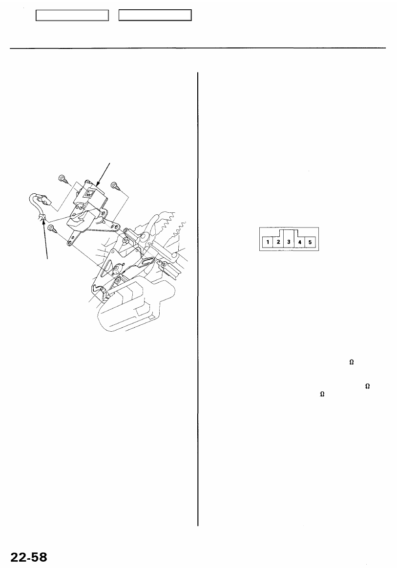
3. Disconnect the wire harness clip and the connector
from the mode control motor, then remove the self-
tapping screws and the mode control motor.
MODE CONTROL MOTOR
WIRE
HARNESS
CLIP
4. Install in the reverse order of removal. After installa-
tion, make sure the mode control motor runs
smoothly.
1. Disconnect the 5P connector from the mode control
motor.
2. Connect battery power to the No. 1 terminal of the
mode control motor and ground the No. 5 terminal;
the mode control motor should run, and stop at
VENT. If it doesn't, reverse the connections; the
mode control motor should run, and stop at DEF.
NOTE: If the mode control motor does not run,
remove it, then check the mode control linkage and
doors for smooth movement. If they move smoothly,
replace the mode control motor.
MODE CONTROL MOTOR
5P CONNECTOR
3. Measure the resistance between the No. 2 and No. 3
terminals. It should be between 4.8 to 7.2 k .
4. Measure the resistance between the No. 3 and No. 4
terminals. It should be between 0.96 to 1.44 k at
VENT and between 3.84 to 5.76 k at DEF.
Main Menu
Table of Contents
Recirculation Control Motor
Replacement
).
2. Remove the glove box back cover (see page
).
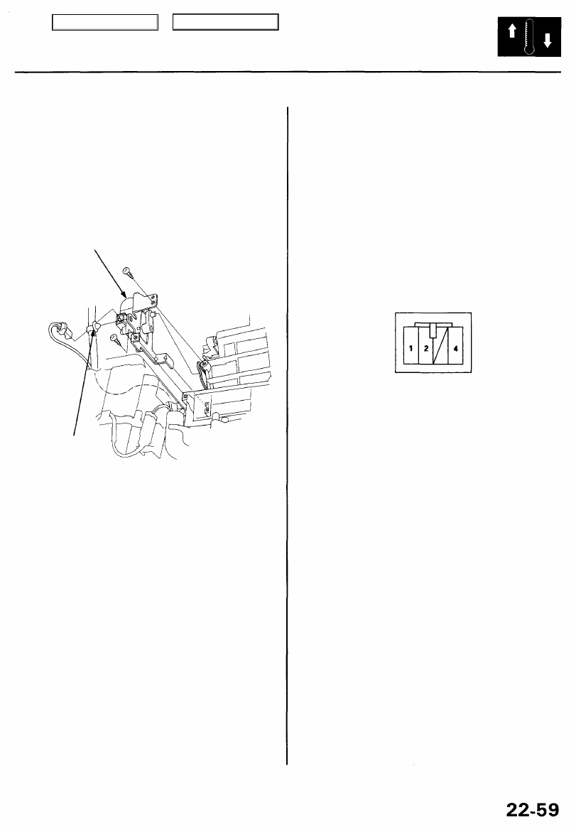
3. Disconnect the wire harness clip and the connector
from the recirculation control motor, then remove
the self-tapping screws and the recirculation control
motor.
RECIRCULATION
CONTROL MOTOR
WIRE
HARNESS
CLIP
4. Install in the reverse order of removal. After installa-
tion, make sure the recirculation control motor runs
smoothly.
Test
1. Disconnect the 4P connector from the recirculation
control motor.
2. Connect battery power to the No. 1 terminal, and
ground the No. 2 and No. 4 terminals; the recircula-
tion control motor should run smoothly.
CAUTION: Never connect the battery in the oppo-
site direction.
RECIRCULATION
CONTROL MOTOR
4P CONNECTOR
3. Disconnect the No. 2 or No. 4 terminals from ground;
the recirculation control motor should stop at
FRESH or RECIRCULATE.
NOTE: Don't cycle the recirculation control motor
for a long time.
4. If the recirculation control motor does not run in
step 2, remove it, then check the recirculation con-
trol linkage and doors for smooth movement. If
they move smoothly, replace the recirculation con-
trol motor.
Main Menu
Table of Contents
In-car Temperature Sensor
Replacement
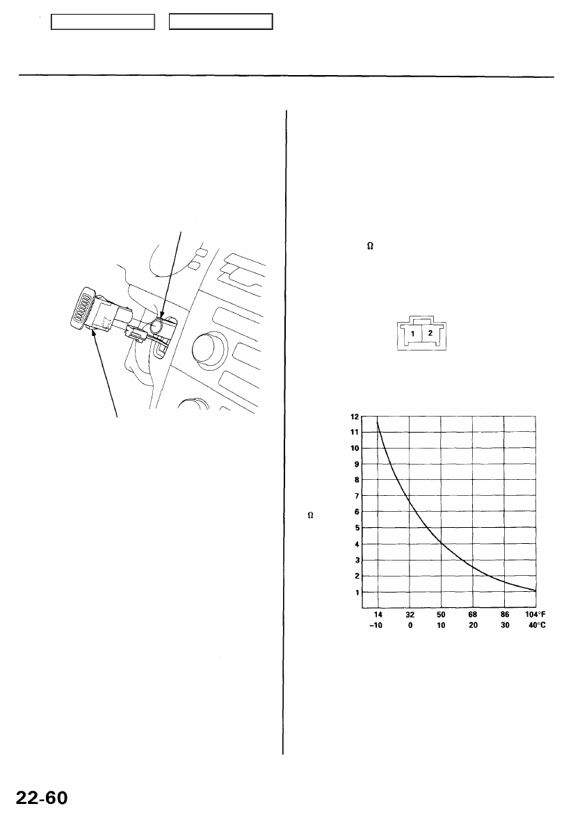
1. Remove the in-car temperature sensor from the
dashboard, then disconnect the connector and the
air hose.
CAUTION: Be careful not to damage the in-car
temperature sensor and the dashboard.
AIR HOSE
IN-CAR TEMPERATURE SENSOR
2. Install in the reverse order of removal.
NOTE: Be sure to connect the air hose securely.
Test
Compare the resistance reading between the No. 1 and
No. 2 terminals of the in-car temperature sensor with
the specifications shown in following graph; resistance
should be within specifications.
NOTE: Check for change in resistance by heating or
cooling the sensor with a hair drier, etc.
CAUTION: The sensor uses a thermistor which can be
damaged if high current is applied during testing.
Therefore, use a circuit tester with an output of 1 mA or
less at the 20 k range.
IN-CAR TEMPERATURE SENSOR
2P CONNECTOR
RESISTANCE
(k )
TEMPERATURE
Main Menu
Table of Contents
Нет комментариевНе стесняйтесь поделиться с нами вашим ценным мнением.
Текст