Acura RL (1996-2004 year). Manual — part 342
6. If the plastigage measures too wide or too narrow,
remove the upper half of the bearing, install a new,
complete bearing with the same color code (select
the color as shown in the right column of this page),
and recheck the clearance.
CAUTION: Do not file, shim, or scrape the bearings
or the caps to adjust clearance.
7. If the plastigage shows the clearance is still incor-
rect, try the next larger or smaller bearing (the color
listed above or below that one), and check clear-
ance again.
NOTE: If the proper clearance cannot be obtained
by using the appropriate larger or smaller bearings,
replace the crankshaft and start over.
NOTE: When using bearing halves of different colors, it
does not matter which color is used in the top or bottom.
Connecting Rod Bearings
Clearance
1. Remove the connecting rod cap and bearing half.
2. Clean the crankshaft rod journal and bearing half
with a clean shop towel.
3. Place a plastigage across strip the rod journal.
4. Reinstall the bearing half and cap, and torque the
nuts to 44 N-m (4.5 kgf-m, 33 Ibf-ft).
NOTE: Do not rotate the crankshaft during inspec-
tion.
5. Remove the rod cap and bearing half, and measure
the widest part of the plastigage.
Connecting Rod Bearing-to-Journal Oil Clearance:
Standard (New): 0.022 - 0.046 mm
(0.0009 - 0.0018 in)
Service Limit: 0.05 mm (0.002 in)
PLASTIGAGE STRIP
Selection
CAUTION: If the codes are indecipherable because of
an accumulation of dirt and dust, do not scrub them
with a wire brush or scraper. Clean them only with sol-
vent or detergent.
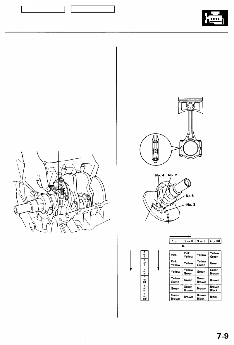
Connecting Rod Code Location
Numbers or bars have been stamped on the side of each
connecting rod as a code for the size of the big end. Use
them, and the letters or bars stamped on the crank
(codes for rod journal size), to choose the correct bear-
ings.
Half of number is
stamped on bearing
cap and the other
half is stamped on
connecting rod.
Connecting Rod Journal Code Locations (Letters or Bars)
Bearing Identification
Color code is on the
edge of the bearing.
Smaller
rod
journal
Smaller
bearing
(thicker)
Small bearing (thicker)
Larger big end bore
No. 6 JOURNAL
(DRIVE PLATE END)
No. 1 JOURNAL
(PULLEY END)
Main Menu
Table of Contents
Pistons and Crankshaft
Removal
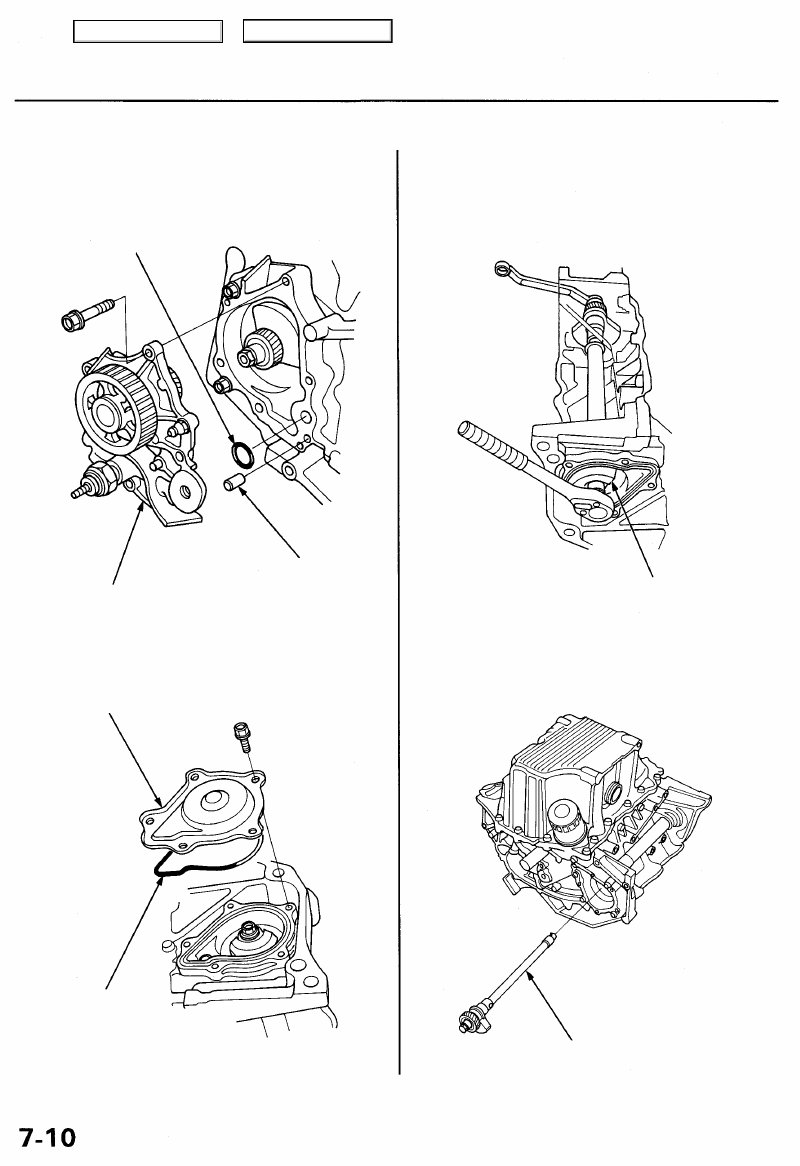
1. Remove the balancer gear case.
O-RING
Replace.
3. Hold the balancer shaft as shown below, then
remove the rear balancer weight.
REAR BALANCER
WEIGHT
4. Pull out the balancer shaft.
NOTE: Take care not to damage the journals when
removing the balancer shaft.
BALANCER GEAR
CASE
DOWEL
PIN
2. Remove the balancer shaft rear cover.
BALANCER SHAFT
REAR COVER
O-RING
Replace.
BALANCER
SHAFT
Main Menu
Table of Contents
5. Remove the balancer shaft holder (see page
).
6. Remove the oil pan assembly.
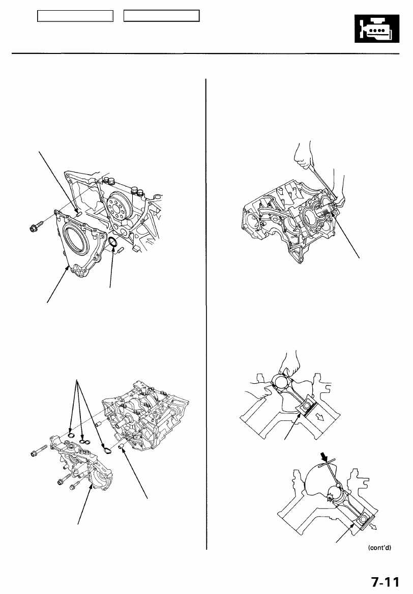
7. Remove the rear cover.
DOWEL
PIN
9. If you can feel a ridge of metal or hard carbon around
the top of any cylinder, remove it with a ridge reamer.
Follow the reamer manufacturer's instructions.
CAUTION: If the ridge is not removed, it may damage
the pistons as they are pushed out.
10. Remove the connecting rod caps after setting the
crank pin at BDC for each cylinder. Remove the pis-
ton assembly by pushing on the connecting rod.
CAUTION: Take care not to damage the crank pin or
cylinder with the connecting rod.
CORRECT
RIDGE REAMER
(Commercially
available)
PISTON
INCORRECT
PISTON
OIL PUMP
DOWEL
PIN
O-RINGS
Replace.
O-RING
Replace.
REAR COVER
8. Remove the oil pump.
Main Menu
Table of Contents
Pistons and Crankshaft
Removal (cont'd)
11. Remove the bearing from the cap. Keep all caps/bear-
ings in order.
12. Remove the upper bearing halves from the connecting
rods, and set them aside with their respective caps.
13. After removing each piston/connecting rod assem-
bly, reinstall the cap on the rod.
14. To avoid mixup during reassembly, mark each pis-
ton/connecting rod assembly with its cylinder num-
ber.
NOTE: The existing number on the connecting rod
does not indicate its position in the engine, it indicates
the rod bore size.
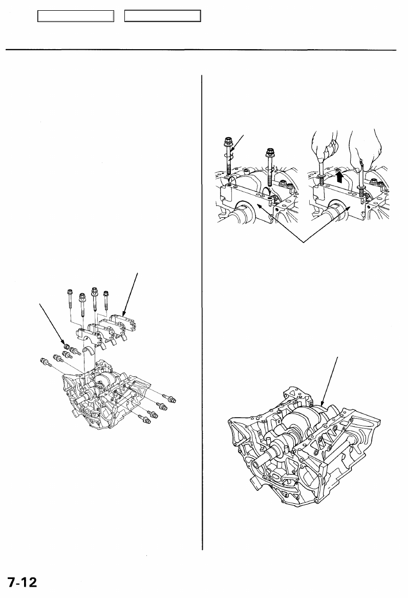
15. Remove the bearing cap bolts and bearing cap side
bolts, then remove the bearing cap.
RUBBER
CAP
MAIN BEARING
CAP
To help with removal of the caps, install the cap bolts in
the outside bolt holes.
CAP BOLT
MAIN BEARING CAPS
16. Lift the crankshaft out of the cylinder block, being
careful not to damage the journals.
CRANKSHAFT
17. Reinstall the main caps and bearings on the cylin-
der block in proper order.
Main Menu
Table of Contents
Нет комментариевНе стесняйтесь поделиться с нами вашим ценным мнением.
Текст