Defender (1999-2002). Manual — part 37

ENGINE
5
OVERHAUL
Refit
1. Thoroughly clean cylinder block and cylinder
head mating faces.
2. Ensure coolant and oil passageways are clear
and bolt holes are clean and dry.
3. Ensure locating dowel holes in cylinder block are
clean and dry.
4. Fit new plastic locating dowels in cylinder block.
5. Fit new cylinder head gasket of the correct
thickness with the word ’TOP’ uppermost.
CAUTION: Gasket must be fitted dry.
6. Ensure that camshaft timing pin LRT-12-158 is
still in position and using assistance, fit cylinder
head.
7. Carefully enter new cylinder head bolts together
with their captive washers, DO NOT DROP.
Lightly tighten bolts.
CAUTION: Cylinder head bolts are
pre-lubricated and do not require
additional lubrication.
8. Using sequence shown, tighten cylinder head
bolts to:
Stage 1 - 30 Nm (23 lbf.ft)
Stage 2 - 65 Nm (48 lbf.ft)
Stage 3 - 90
°
Stage 4 - Further 180
°
Stage 5 - Further 45
°
CAUTION: Ensure correct tightening
sequence is followed for all 5 tightening
stages. Do not tighten bolts 315
°
in one
operation.
9. Fit cylinder head to timing chain cover nut and
bolt and tighten to 25 Nm (18 lbf.ft) .
10. Clean camshaft sprocket and mating face on
camshaft.
11. Ensure engine is set to TDC firing - No.1
cylinder.
12. Check that mark on camshaft sprocket is
positioned between the 2 coloured links on
timing chain.
13. Position sprocket to camshaft, fit and lightly
tighten 3 new bolts then loosen bolts half a turn.
12
ENGINE
6
OVERHAUL
14. Clean fixed guide Allen screw and apply Loctite
242 to screw threads.
15. Fit fixed timing chain guide Allen screw and
tighten to 25 Nm (18 lbf.ft) .
16. Clean timing chain tensioner and fit new sealing
washer.
17. Fit timing chain tensioner and tighten to 45 Nm
(33 lbf.ft) .
18. Tighten camshaft sprocket bolts to 36 Nm (27
lbf.ft) .
19. Remove tool LRT-12-058 from camshaft.
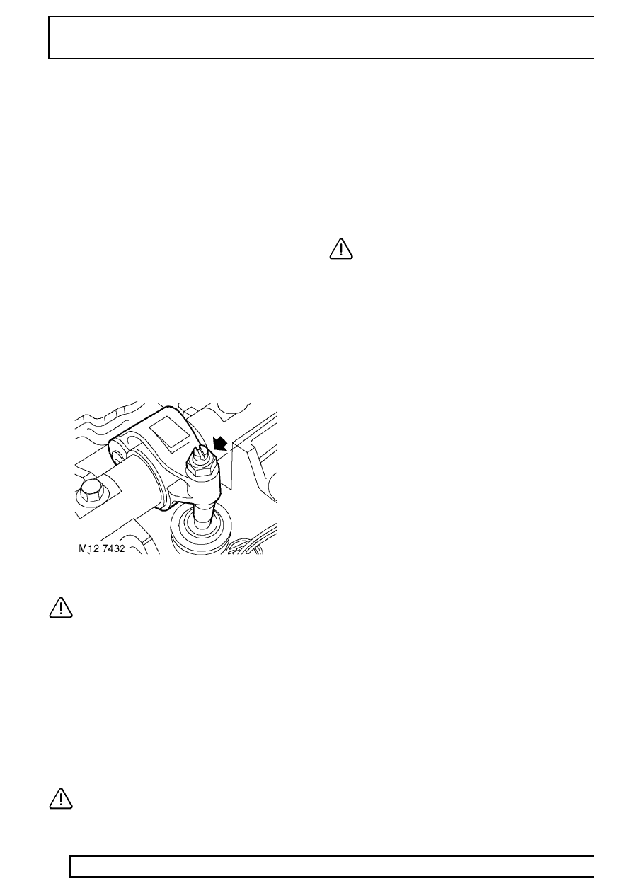
20. Lubricate a new ’O’ ring with engine oil and fit to
camshaft sprocket access plug.
21. Fit camshaft sprocket access plug.
22. Clean alternator/vacuum pump oil feed hose
union.
23. Lubricate a new ’O’ ring with engine oil and fit to
alternator/vacuum pump hose union.
24. Fit and tighten alternator/vacuum pump oil hose
union to 10 Nm (7 lbf.ft) .
25. Fit bolt securing alternator strap bracket to
cylinder head and tighten to 25 Nm (18 lbf.ft) .
26. Connect multiplugs to ECT sensor and EUIs.
CAUTION: Following cylinder head
overhaul, it will be necessary, before
fitting the camshaft cover, to adjust the
fuel injector rockers using the following
procedures:
27. Rotate engine clockwise until No. 1 EUI lobe is
at full lift.
28. Tighten No.1 rocker adjusting screw until the EUI
plunger is felt to ’bottom out’.
29. Loosen rocker adjusting screw 1 complete turn
to give EUI plunger the required bump clearance
and tighten rocker adjusting screw locknut to 16
Nm (12 lbf.ft) .
CAUTION: Ensure screw does not turn as
locknut is tightened.
30. Carry out above procedures for the remaining 4
rocker arms.
31. After completion of rocker adjustment, slowly
rotate engine clockwise 2 complete turns by
hand to ensure that no EUI’s are bottoming out
on their plungers.
32. Clean camshaft cover and mating face.
33. Fit new sealing washers and isolators as
necessary to camshaft cover.
34. Fit new camshaft cover gasket to cover.
CAUTION: Gasket must be fitted dry.
35. Fit camshaft cover to camshaft carrier, fit bolts
and working from the centre outwards, tighten
bolts to 10 Nm (7 lbf.ft) .
36. Fit inlet manifold gasket. See MANIFOLD AND
EXHAUST SYSTEM, Repair.
37. Fit exhaust manifold gasket. See MANIFOLD
AND EXHAUST SYSTEM, Repair.
38. EGR cooler fitted:- Position EGR pipe to cooler,
fit new Allen screws and tighten to 10 Nm (7
lbf.ft).

ENGINE
7
OVERHAUL
CYLINDER HEAD GASKET SELECTION
NOTE: There are three thicknesses of
cylinder head gasket available and in order
that the correct gasket is fitted, it will be
necessary to determine the stand proud
(protrusion) of each piston above the top face of
the cylinder block. Gaskets have either 1, 2 or 3
identification holes and the following procedures
must be followed in order that the correct gasket
is selected.
1. Temporarily fit and lightly tighten a new
crankshaft pulley bolt.
2. Assemble a magnetic base DTI to cylinder block
top face adjacent to No. 1 cylinder bore.
3. Position stylus to cylinder block top face and
zero gauge.
4. Using crankshaft pulley bolt, rotate crankshaft in
a clockwise direction until No.1 piston is at TDC -
Woodruff key slot in crankshaft is at 12 o’clock.
5. Position stylus of DTI at edge of piston and
directly over gudgeon pin axis.
6. Measure and record No.1 piston protrusion.
CAUTION: Measurement must be taken at
front and rear of piston.
7. Establish average of the 2 readings taken.
8. Repeat above procedures for remaining pistons.
9. From readings obtained, determine HIGHEST
piston protrusion figure and select the
appropriate cylinder head gasket:
Piston protrusion = 0.351 to 0.50 mm (0.014 to
0.02 in) - Select the 2 hole gasket.
Piston protrusion = 0.501 to 0.57 mm (0.021 to
0.022 in) - Select the 1 hole gasket.
Piston protrusion = 0.571 to 0.65 mm (0.022 to
0.025 in) - Select the 3 hole gasket.
10. Remove DTI.
11. Fit cylinder head gasket. See this Section.

12
ENGINE
8
OVERHAUL
CYLINDER HEAD - OVERHAUL
Service repair no - 12.29.19.01
Dismantling
1. Remove cylinder head gasket. See this
Section.
CAUTION: Due to the design of the
cylinder head which incorporates drillings
for the fuel injection system, it is important
that absolute cleanliness is adhered to when
carrying out overhaul procedures.
2. Note the gasket thickness indicator and ensure
the same thickness gasket is used on refitment
of cylinder head.
CAUTION: If new pistons, connecting rods
or crankshaft are fitted, it will be
necessary to determine thickness of
gasket required. See this Section.
3. Remove 4 glow plugs.
4. Disconnect multiplugs from EUI’s and remove
harness from camshaft carrier. Remove and
discard ’O’ ring from harness multiplug.
5. Loosen lock nuts and fully unscrew rocker
adjusting screws; discard locknuts and screws.
6. Remove and discard 6 bolts securing rocker
shaft, remove shaft.
NOTE: Dowel located.
7. Using sequence shown, progressively loosen 13
bolts securing camshaft carrier to cylinder head
until valve spring pressure is released; remove
bolts.
CAUTION: Do not discard bolts at this
stage.
Нет комментариевНе стесняйтесь поделиться с нами вашим ценным мнением.
Текст