Defender (1999-2002). Manual — part 38

ENGINE
9
OVERHAUL
8. Gently tap camshaft carrier upwards to break
sealant bond, remove carrier.
NOTE: Dowel located.
9. Remove camshaft.
10. Remove and discard camshaft rear oil seal.
11. Remove finger followers and lash adjusters.
CAUTION: Store lash adjusters and finger
followers in their fitted order and store
lash adjusters upright. Maintain absolute
cleanliness when handling components.
12. Remove and discard 5 bolts securing EUI
retainers.
13. Using tool LRT-12-154/1 remove EUI units from
cylinder head and collect retainers. Remove
reaction posts and keep in their fitted order.
14. Using tool LRT-12-154/4, remove and discard
sealing washer and ’O’ ring from each EUI unit.
15. Support cylinder head clear of valves, use a
hollow drift and tap each valve spring cap to free
collets.
16. Using tool LRT-12-034, compress valve spring.
17. Remove 2 collets from valve stem using a stick
magnet.
18. Remove tool LRT-12-034.
19. Remove valve spring cap, valve spring and
valve.
CAUTION: Keep components in their fitted
order.
12
ENGINE
10
OVERHAUL
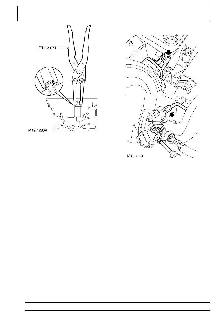
20. Using tool LRT-12-071, remove and discard
valve stem oil seal.
21. Repeat above operations to remove remaining
valves.
22. Engine Serial No. Prefixes 15P to 19P:-
Disconnect spill return pipe from cylinder head
and fuel connector block, remove and discard ’O’
rings.
ENGINE
11
OVERHAUL
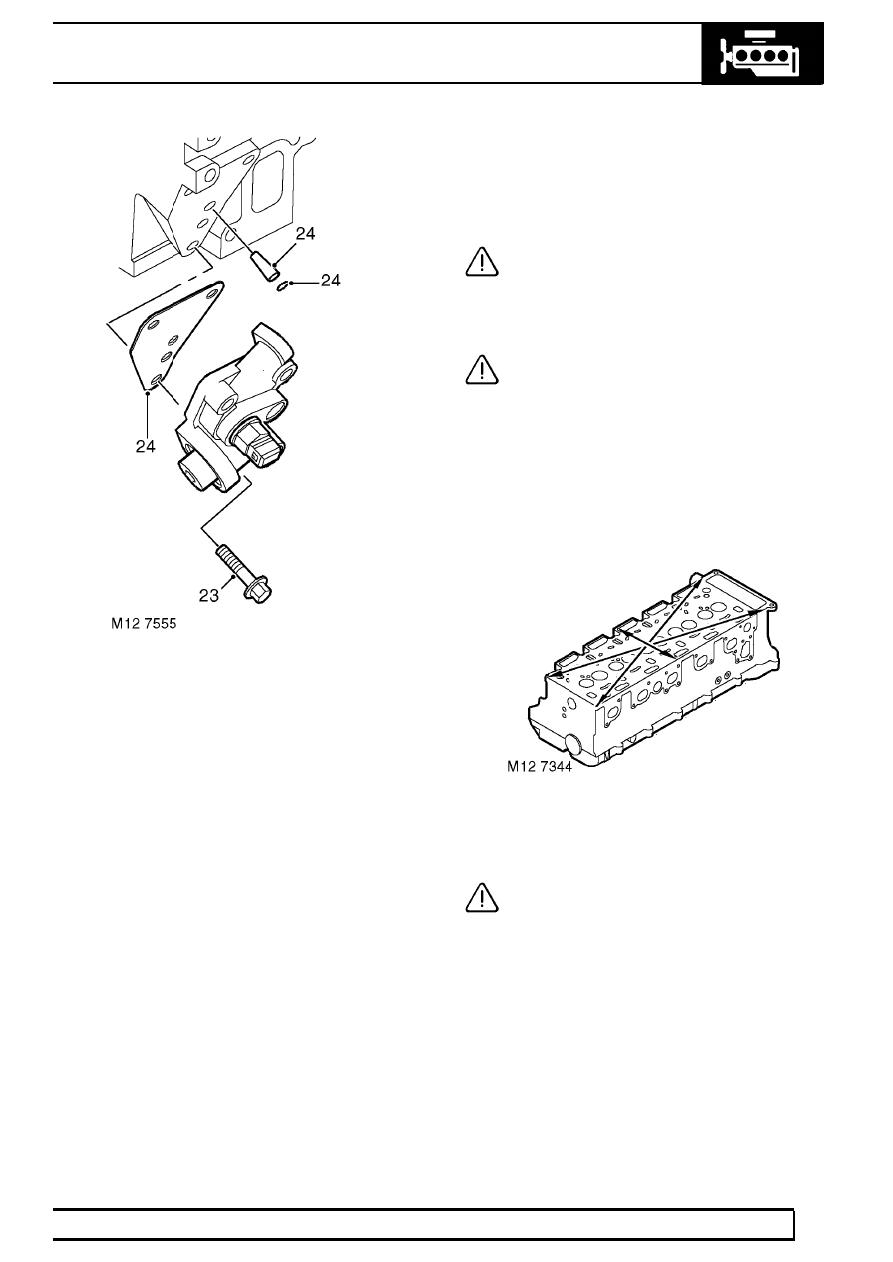
23. Remove 3 bolts and remove fuel connector
block from cylinder head.
24. Remove and discard gasket, ’O’ ring and fuel
filter.
25. Remove spacer block and gasket (if fitted).
Cylinder head and camshaft carrier - cleaning
1. Thoroughly clean cylinder head mating faces,
ensure oil and coolant passages are clear and
bolt holes are clean and dry.
CAUTION: Take care to ensure that EUI
drillings are clear.
2. Using suitable solvent, remove all traces of
sealant and gasket material.
CAUTION: Do not use metal scrapers.
3. Remove all traces of oil from camshaft bearings
and journals.
4. Clean glow plug threads.
Cylinder head - Inspection
1. Check core plugs for signs of leakage and
corrosion, seal replacement plugs with Loctite
243.
2. Check cylinder head for warping across centre
and from corner to corner.
Maximum cylinder head warp = 0.1 mm (0.004
in).
CAUTION: Cylinder heads may not be
refaced, replace the head assembly if
warping exceeds the limit given.

12
ENGINE
12
OVERHAUL
Lash adjusters and finger followers - Inspection
1. Check lash adjuster bores for scoring and signs
of wear or damage.
2. Check lash adjusters for signs of wear, scoring
and overheating, replace as necessary. Ensure
oil hole in each lash adjuster is clear.
CAUTION: Store lash adjusters upright
and in their fitted order.
3. Check finger followers for wear and that rollers
are free to rotate.
CAUTION: Store finger followers in their
fitted order.
Camshaft - Inspection
1. Check camshaft lobes and bearing journals for
signs of scoring and wear.
2. Check bearing surfaces in cylinder head and
camshaft carrier for signs of scoring and wear.
CAUTION: Cylinder head and camshaft
carrier are machined together as an
assembly, if bearing surfaces in either
component are damaged, both components must
be replaced as an assembly.
Camshaft - Check end-float
1. Position camshaft in camshaft carrier.
2. Check end-float of camshaft using a DTI.
Camshaft end-float = 0.06 to 0.16 mm (0.002 to
0.006 in).
3. Renew components as necessary to achieve
correct end-float.
Нет комментариевНе стесняйтесь поделиться с нами вашим ценным мнением.
Текст