Defender (1999-2002). Manual — part 84
47
PROPELLER SHAFTS
2
REPAIR
Refit
7. Grease propeller shaft universal joints.
8. Grease propeller shaft spline.
9. Clean propeller shaft flange mating faces.
10. Fit propeller shaft to park brake flange bolts.
NOTE: Ensure relationship marks align.
11. Position propeller shaft to rear axle flange and fit
bolts.
12. Fit nuts and bolts securing propeller shaft to rear
axle flange and tighten to 48 Nm (35 lbf.ft).
NOTE: Rotation of propeller shaft may be
required during the above procedure.
13. Fit nuts securing propeller shaft to park brake
and tighten to 48 Nm (35 lbf.ft).
NOTE: Rotation of propeller shaft may be
required during the above procedure.
14. Remove stand(s) and lower vehicle.

PROPELLER SHAFTS
1
OVERHAUL
PROPELLER SHAFT - FRONT
Service repair no - 47.15.11
Remove
1. Remove front propeller shaft. See Repair.
2. Thoroughly examine universal joints for signs of
damage or wear.
3. Clean universal joint bearing cups and circlips.
CAUTION: To ensure correct assembly
and reduce possibility of imbalance,
before removing propeller shaft joint mark
position of spider pin relative to journal yoke ears.
4. Remove circlips.
5. Note position and remove grease nipple.
6. Tap yokes to eject bearing cups.
7. Remove bearing cups.
8. Remove spider.
9. Clean yokes and bearing cup locations.
Refit
10. Remove bearing cups from new spider.
11. Check all needle rollers are present and
positioned in bearing cups.
12. Enter new spider with seals into yokes of
propeller shaft flange.
13. Partially insert one bearing cup into flange yoke
and enter spider trunnion into bearing cup.
14. Insert opposite bearing cup into flange yoke.
15. Press both cups into place.
16. Press each cup into its respective yoke up to
lower land of circlip groove. Damage may be
caused to cups and seals if cups pass this point.
17. Fit circlips and check no end float exists.
18. Fit grease nipple and lubricate
19. Repeat instructions for opposite end of propeller
shaft as described in 1 to 9.
20. Fit front propeller shaft. See Repair.

47
PROPELLER SHAFTS
2
OVERHAUL
PROPELLOR SHAFT - REAR
Service repair no - 47.15.12
Remove
1. Remove rear propeller shaft. See Repair.
2. Thoroughly examine universal joint for signs of
damage or wear.
3. Clean universal joint bearing cups and circlips.
CAUTION: To ensure correct assembly
and reduce possibility of imbalance,
before removing propeller shaft joint mark
position of spider pin relative to journal yoke ears.
4. Remove circlips.
5. Remove grease nipple.
6. Tap yokes to eject bearing cups.
7. Remove bearing cups.
8. Remove spider.
9. Clean yokes and bearing cup locations.
Refit
10. Remove bearing cups from new spider.
11. Check all needle rollers are present and
positioned in bearing cups.
12. Enter new spider with seals into yokes of
propeller shaft flange.
13. Partially insert one bearing cup into flange yoke
and enter spider trunnion into bearing cup.
14. Insert opposite bearing cup into flange yoke.
15. Press both cups into place.
16. Press each cup into its respective yoke up to
lower land of circlip groove. Damage may be
caused to cups and seals if cups pass this point.
17. Fit circlips and check no end float exists.
18. Fit grease nipple and lubricate.
19. Repeat instructions for opposite end of propeller
shaft as described in 3 to 9.
20. Fit rear propeller shaft. See Repair.
STEERING
1
REPAIR
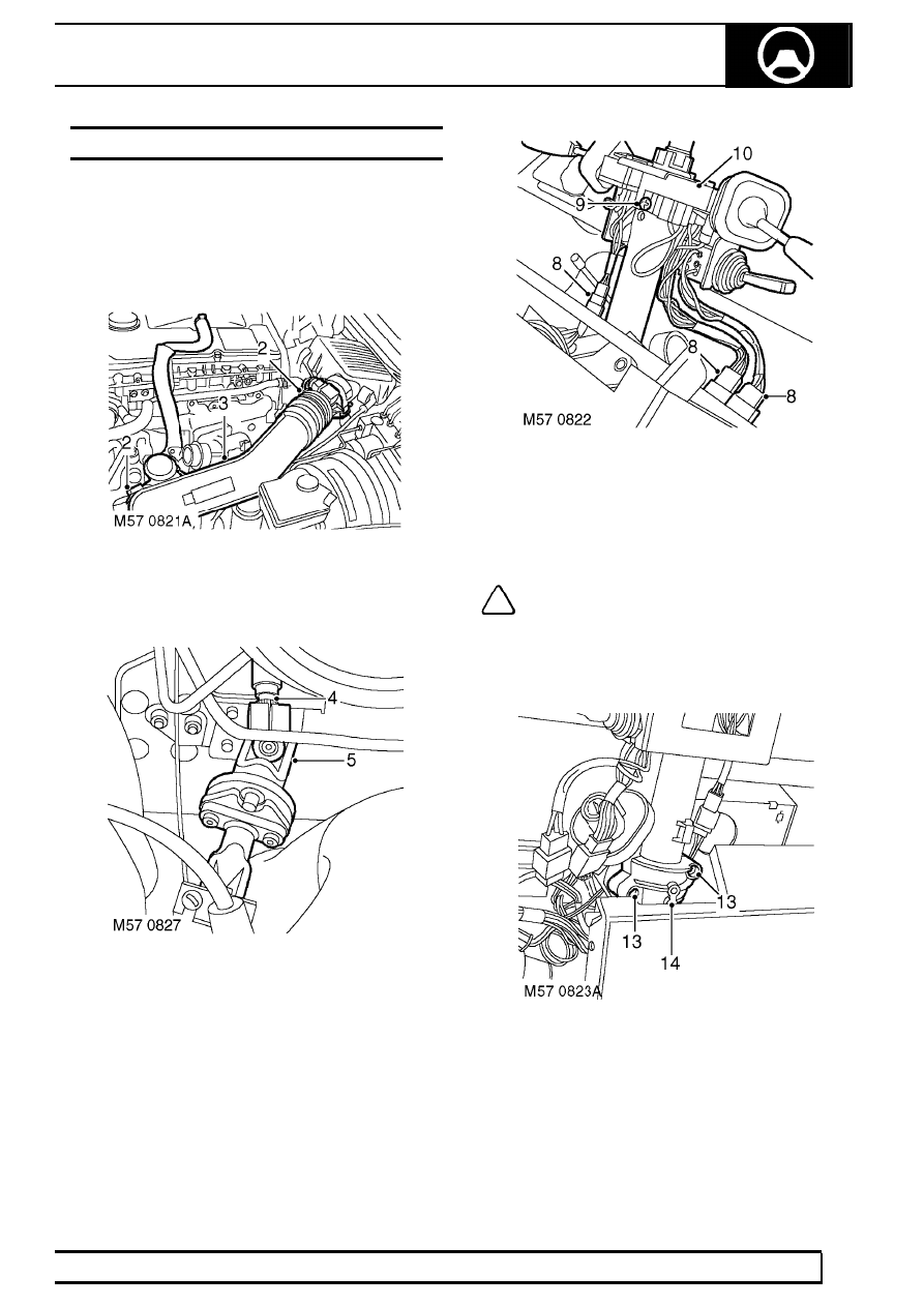
STEERING COLUMN - UPPER - Td5
Service repair no - 57.40.01
Remove
1. Ensure road wheels and steering wheel are set
in the straight ahead position.
2. Loosen 2 clips securing air inlet pipe between
turbo and inlet air filter.
3. Remove air inlet pipe.
4. Mark relationship between the upper steering
column and the lower steering column universal
joint.
5. Remove bolt securing upper column to lower
column universal joint.
6. Remove steering colum nacelle. See this
Section.
7. Remove instrument pack. See
INSTRUMENTS, Repair.
8. Disconnect 3 column switch multiplugs.
9. Loosen column switch clamping screw.
10. Remove column switch assembly from steering
column.
11. Disconnect 4 Lucars from rear of ignition switch.
NOTE: Take note of Lucars correct fitted
position. Details can also be found in the
Electrical Reference Library.
12. Remove passive coil. See ELECTRICAL,
Repair.
13. Drill out 2 shear bolts securing ignition barrel to
column.
14. Remove ignition barrel.
Нет комментариевНе стесняйтесь поделиться с нами вашим ценным мнением.
Текст