Defender (1999-2002). Manual — part 85

57
STEERING
2
REPAIR
15. Remove brake servo. See BRAKES, Repair.
16. Release ABS modulator multiplug from side of
brake pedal box.
17. Release mat from underside of fascia to gain
access to brake pedal box mounting bolts.
18. Remove 6 bolts securing brake pedal box to
bulkhead.
19. Disconnect 2 brake pedal switch Lucars.
20. Carefully remove brake pedal box assembly and
collect gasket.
21. Remove bolt securing column upper tie bar to
column.
22. Remove 2 bolts securing upper column to lower
mounting bracket.
23. Remove 2 bolts securing 2 halves of column
upper clamp.
24. Remove 2 bolts securing column upper clamp to
mounting bracket.
25. Remove column upper clamp and collect rubber
packing.
26. Remove 2 bolts securing column upper
mounting bracket to bulkhead.
27. Release upper column from lower column and
manouvre mounting bracket and upper column
assembly from vehicle.
28. Remove mounting bracket from column.
STEERING
3
REPAIR
Refit
NOTE: The steering column is a
non-servicable component and can only
be serviced as a complete assembly.
29. Fit mounting bracket to column and manouvre
assembly into position.
NOTE: Ensure marks on upper and lower
columns are aligned.
30. Loosely fit bolts securing mounting bracket to
bulkhead.
31. Fit upper clamp and rubber packing to column.
32. Loosely fit bolts securing upper clamp to
mounting bracket.
33. Loosely fit bolts securing 2 halves of upper
clamp.
34. Loosely fit bolts securing column lower mounting
bracket.
35. Fit bolt securing upper tie bar to steering column
and tighten to 22 Nm (16 lbf.ft) .
36. Tighten mounting bracket to bulkhead bolts,
clamp bolts, and lower mounting bolts.
M6 bolts = 9 Nm (6 lbf.ft)
M8 bolts = 22 Nm (16 lbf.ft)
37. Manouvre brake pedal box assembly and NEW
gasket into position in vehicle.
38. Tighten bolts securing brake pedal box to
bulkhead to 25 Nm (18 lbf.ft)
39. Connect brake pedal switch Lucars.
40. Reposition mat to underside of fascia.
41. Secure ABS modulator multiplug to side of brake
pedal box.
42. Fit brake servo. See BRAKES, Repair.
43. Fit ignition switch to steering column, ensuring
inner shaft slot aligns with steering lock plunger.
44. Evenly tighten clamp bolts, but DO NOT shear at
this stage.
45. Temporarily fit steering wheel and check for
correct operation of switch and lock.
46. Remove steering wheel.
47. Fully tighten ignition switch bolts until heads
shear.
48. Connect Lucars to rear of ignition switch.
49. Fit passive coil to ignition switch and connect
multiplug.
50. Fit switch assembly to steering column and
tighten clamping screw.
51. Connect column switch multiplugs.
52. Fit instrument pack. See INSTRUMENTS,
Repair.
53. Fit steering column nacelle. See this Section.
54. Fit bolt securing upper column to lower column
universal joint and tighten to 25 Nm (18 lbf.ft) .
55. Fit air inlet pipe between turbo and inlet air filter
and secure with clips.
FRONT SUSPENSION
1
DESCRIPTION AND OPERATION
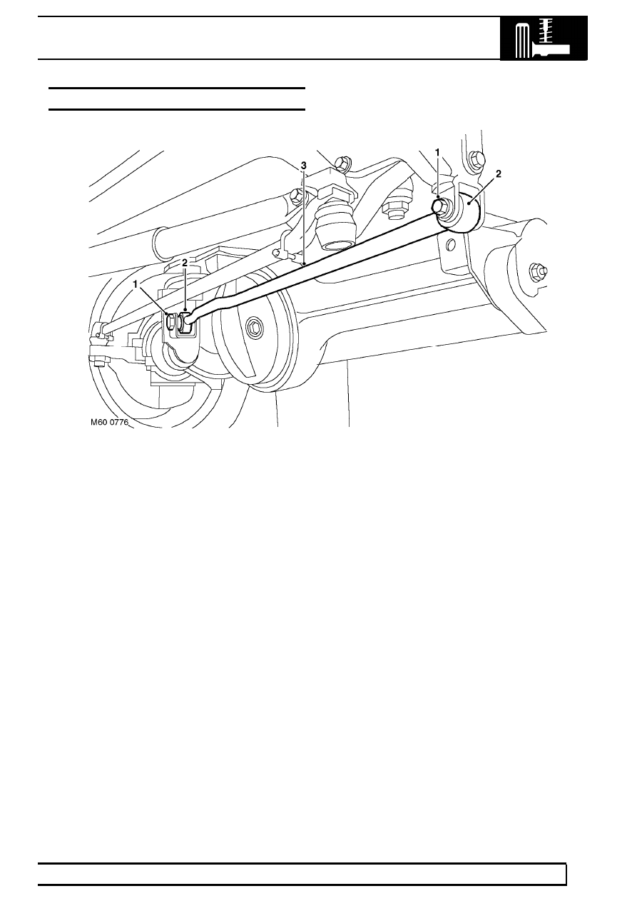
FRONT SUSPENSION - FROM 02MY
1. Bolts
2. Bushes
3. Panhard rod
Changes have been incorporated to improve the durability of the suspension. The current Panhard rods are
forged. New Panhard rods are introduced which are fabricated from tubular steel and are handed.
The rods are fitted with larger bushes which use M16 bolts in place of the M14 bolts. The torque for the new bolts
is raised to 230 Nm (170 lbf.ft).
The Panhard rod support brackets are now fabricated from upgraded steel which allows the higher torque figure to
be applied to the fixing bolts.

FRONT SUSPENSION
1
REPAIR
PANHARD ROD - FROM 02MY
Service repair no - 60.10.07.
Remove
1. Remove fixings at mounting arm.
2. Remove fixings at axle bracket.
3. Remove panhard rod.
4. Using a suitable length of steel tubing, press out
flexible bushes. Ensure tubing locates on outer
edge of bush and not on rubber inner.
Refit
5. Fit replacement bushes.
CAUTION: Apply pressure to outer edge of
bush, and not rubber inner.
6. Fit panhard rod to axle bracket and mounting
arm. Tighten fixings to 230 Nm (170 lbf/ft).
BEARINGS - FRONT HUB
Service repair no - 60.25.14
Remove
1. Raise front of vehicle.
WARNING: Support on safety stands.
2. Remove front road wheel.
3. Pull back front brake caliper jump hose shield
and clamp brake hose.
4. Position container collect brake fluid.
5. Loosen brake pipe to jump hose union and
disconnect.
CAUTION: Use 2 spanners when loosening
or tightening unions.
6. Remove 2 bolts securing brake caliper to hub.
7. Remove brake caliper.
CAUTION: Plug the connections.
8. Remove dust cap.
9. Remove circlip and shim(s) from drive shaft.
10. Remove and discard 5 bolts securing driving
member to hub.
11. Remove driving member and discard gasket.
Нет комментариевНе стесняйтесь поделиться с нами вашим ценным мнением.
Текст