Defender. Manual — part 26
3. NOTE: Install new nuts.
Tighten to 47 Nm (35 lb.ft).
Align the position of the driveshaft in relation to the
drive pinion flange.
Driveshaft - Rear Driveshaft
Removal and Installation
Removal
1.
WARNING: Support on safety stands and chock front
wheels.
Raise rear of vehicle.
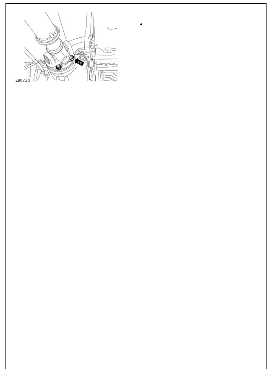
2. NOTE: Mark the rear driveshaft to parking brake flange.
Remove and discard 4 nuts securing driveshaft to parking
brake flange.
• NOTE: Rotation of driveshaft may be required during the above procedure.
3. NOTE: Mark the rear driveshaft to rear differential flange.
• NOTE: Rotation of driveshaft may be required during the
procedure.
Remove and discard 4 nuts securing driveshaft to rear axle
flange.
4. Release driveshaft from parking brake flange.
5. Remove driveshaft.
Installation
1. Clean driveshaft flange mating faces.
2. Fit driveshaft to park brake flange bolts.
• NOTE: Ensure relationship marks align.
3. Position driveshaft to rear axle flange and fit bolts.
4. NOTE: Rotation of driveshaft may be required during the
procedure.
Fit nuts and bolts securing driveshaft to rear axle flange and
tighten to 47 Nm (35 lbf.ft).
5. Fit nuts securing driveshaft to park brake and tighten to 50
Nm (37 lbf.ft).
• NOTE: Rotation of driveshaft may be required during the procedure.
6. Remove stands and lower vehicle.
7. Apply parking brake.
Driveshaft - Driveshaft Universal Joint
Disassembly and Assembly
Disassembly
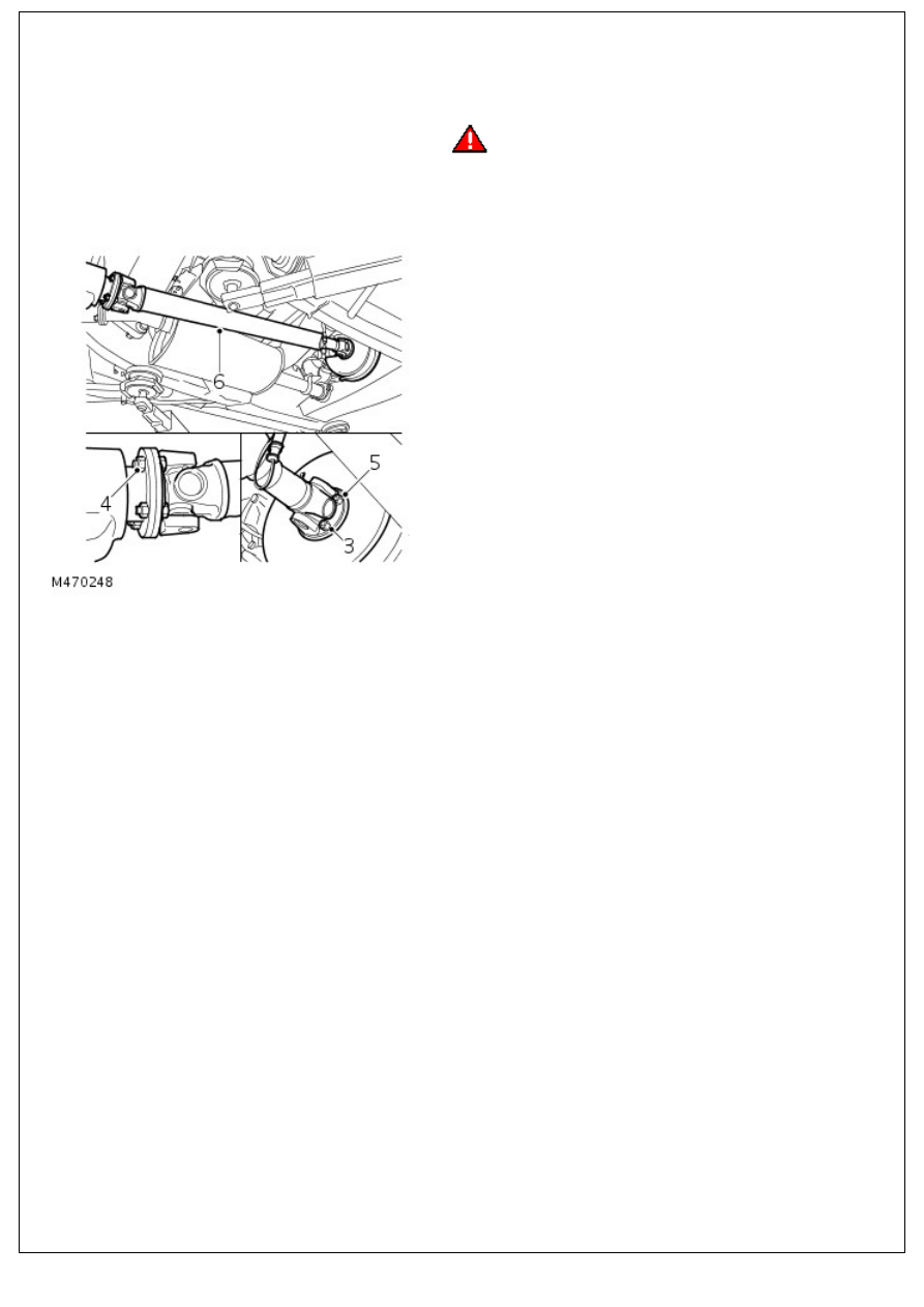
1. Remove driveshaft. For additional information, refer to:
(205-01 Driveshaft)
Front Driveshaft
(Removal and Installation),
Rear Driveshaft
(Removal and Installation).
2. Thoroughly examine universal joints for signs of damage or
wear.
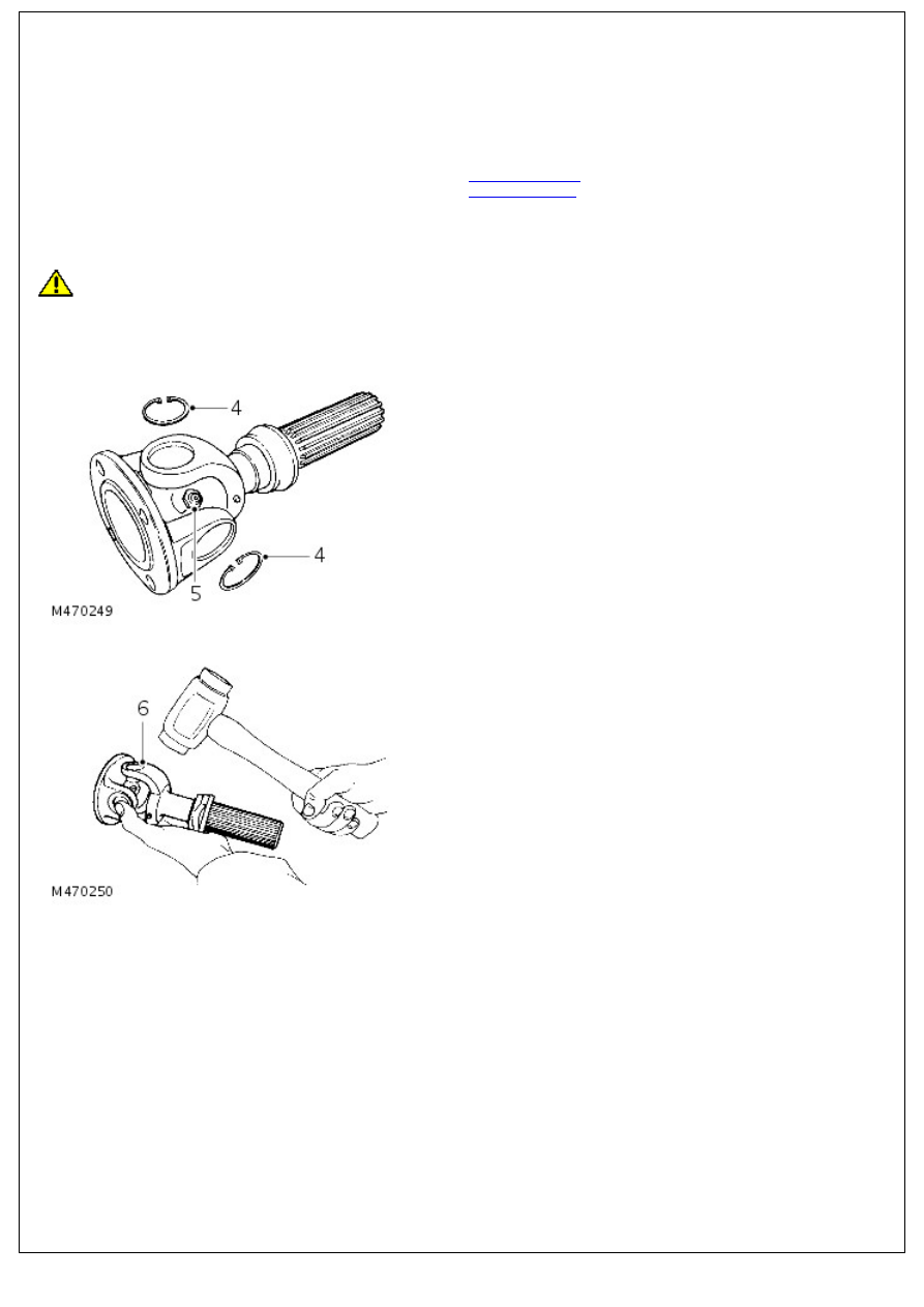
3. Clean universal joint bearing cups and circlips.
CAUTION: To ensure correct assembly and reduce possibility of imbalance, before removing driveshaft joint mark
position of spider pin relative to journal yoke ears.
4. Remove circlips.
5. Note position and remove grease nipple.
6. Tap yokes to eject bearing cups.
7. Remove bearing cups.
8. Remove spider.
9. Clean yokes and bearing cup locations.
Assembly
1. Remove bearing cups from new spider.
2. Check all needle rollers are present and positioned in bearing
cups.
3. Enter new spider with seals into yokes of propeller shaft
3. Enter new spider with seals into yokes of propeller shaft
flange.
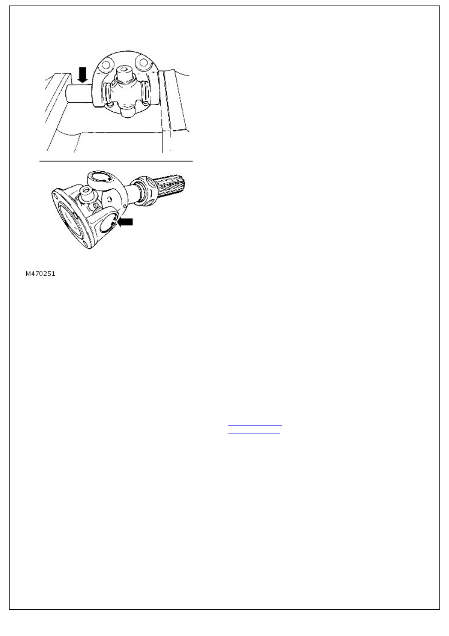
4. Partially insert one bearing cup into flange yoke and enter
spider trunnion into bearing cup.
5. Insert opposite bearing cup into flange yoke.
6. Press both cups into place.
7. Press each cup into its respective yoke up to lower land of
circlip groove. Damage may be caused to cups and seals if
cups pass this point.
8. Fit circlips and check no end float exists.
9. Fit grease nipple and lubricate
10. Repeat instructions for opposite end of driveshaft as
described in 3 to 9.
11. Fit driveshaft. For additional information, refer to: (205-01
Driveshaft)
Front Driveshaft
(Removal and Installation),
Rear Driveshaft
(Removal and Installation).
Нет комментариевНе стесняйтесь поделиться с нами вашим ценным мнением.
Текст