Defender. Manual — part 25
Wheels and Tires - Wheel and Tire
Removal and Installation
Removal
WARNING: The parking brake acts on transmission, not rear wheels, and may not hold vehicle when jacking unless
following procedure is used. If one front wheel and one rear wheel is raised no vehicle holding or braking effect is
possible. Wheels MUST be chocked in all circumstances.
1. Apply parking brake, select a gear in main gearbox and
engage low gear in transfer box.
2. Loosen 5 wheel nuts.
3. Using a suitable trolley jack, raise vehicle and place on axle
stands.
For additional information, refer to:
Jacking
(100-02 Jacking
and Lifting, Description and Operation).
4. Remove wheel nuts and carefully withdraw wheel over studs.
Installation
1. Ensure that retaining studs and nuts are clean.
2. Alloy wheels: Lightly coat wheel mounting spigot face with
a suitable anti-seize compound to minimise possibility of
adhesion between wheel and spigot face.
3. Refit wheel taking care not to damage stud threads. (Do not
apply oil).
4. Fit wheel nuts and turn by hand for at least three full
threads before using any form of wheel wrench.
5. Tighten nuts as much as possible using a suitable wrench.
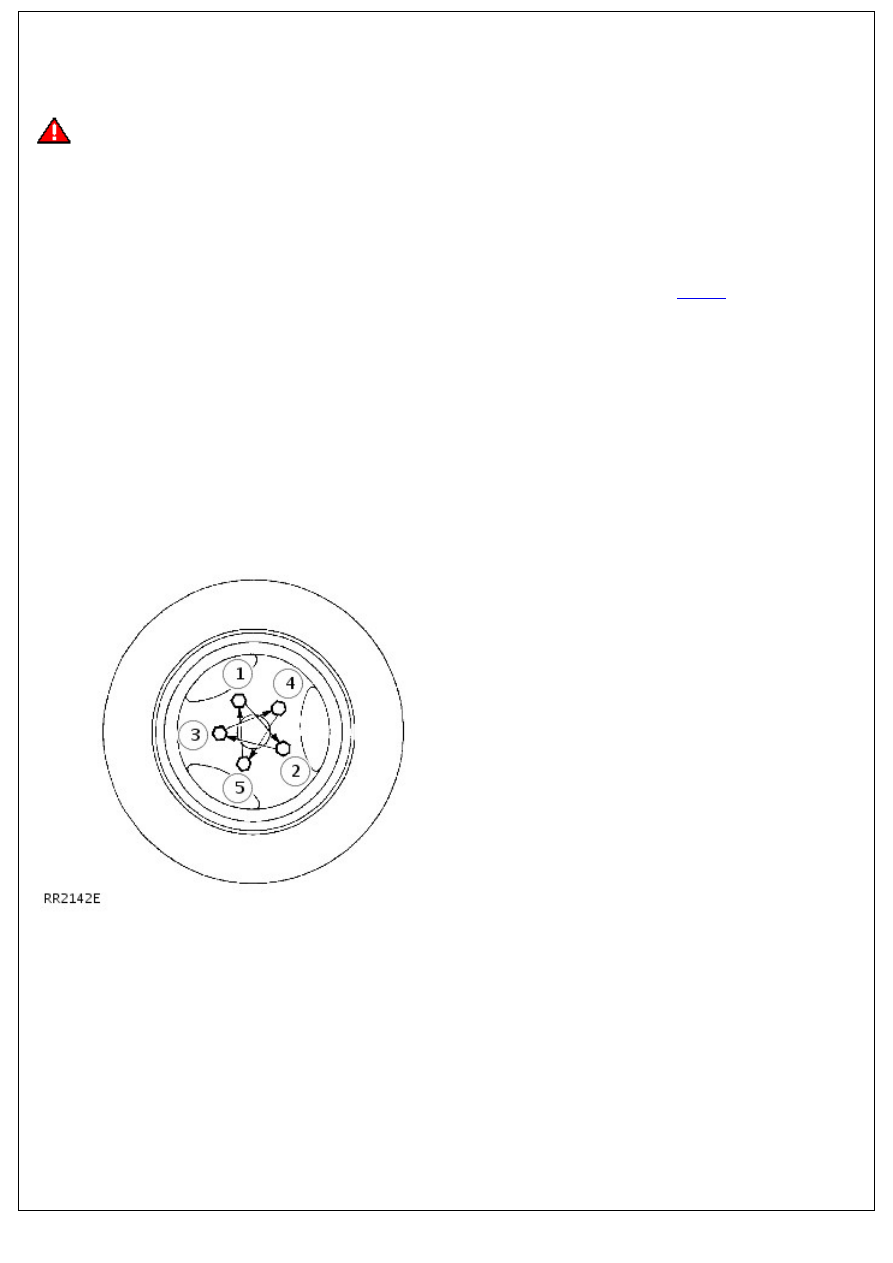
6. Lower vehicle and finally tighten nuts to correct torque
sequence shown.
1. Alloy wheels - 130 Nm
2. Steel wheels - 100 Nm
3. Heavy duty wheels - 170 Nm
Vehicle Dynamic Suspension - Rear Air Shock Absorber
Removal and Installation
Removal
WARNING: The self-levelling unit contains pressurised gas and MUST NOT be dismantled. Repair is by replacement
of complete unit only.
• NOTE: This procedure covers the suspension self-levelling unit.
1. Raise and support the vehicle under chassis and use a jack
to support weight of the axle.
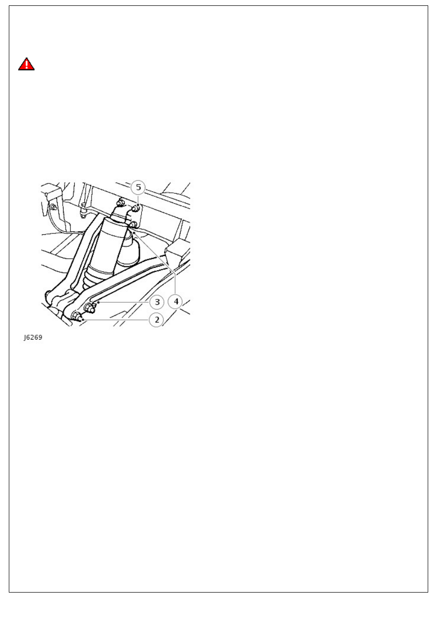
2. Disconnect upper links at pivot bracket.
3. Ease up self-levelling unit lower gaiter and unscrew lower
ball joint at push rod using thin jawed spanners.
4. Release webbing strap from the chassis.
5. Remove 4 nuts securing top bracket to chassis and
withdraw self-levelling unit complete with bracket.
6. Renew self-levelling unit ball joints
7. Unscrew lower ball joint from pivot bracket.
8. Unscrew ball joint from top bracket.
9. Reassemble ball joints, packing with Dextagrease G.P. or
equivalent. Renew joints if worn.
10. Check condition of gaiters and renew if necessary.
Installation
1. Ensure ball pin threads are clean and smear Loctite grade
CVX on ball pin threads.
2. Fit upper ball joint to self-levelling unit and secure gaiter.
3. Fit top bracket complete with levelling unit to chassis and
secure with 4 nuts and tighten to 47 Nm (35 lbf/ft).
4. Fit self-levelling unit to lower ball joint and secure gaiter.
5. Attach webbing strap to chassis cross member.
6. Fit upper links to the pivot bracket and retain with 2 bolts
and nuts but do not tighten at this stage.
7. Remove jack in support of axle and support from under
chassis.
8. Allow suspension to settle and then tighten 2 bolts and nuts
retaining upper links to pivot bracket to 176 Nm (130 lbf/ft).
Driveshaft - Driveshaft
Description and Operation
Description
The front and rear drive shafts have non-constant velocity type universal joints, with needle roller bearings. The bearing
cups are pre-packed with lubricant on assembly and a grease nipple is fitted for servicing as specified, in maintenance
section.
Both shafts have ball splines to accommodate the variation in distance between the axles and transmission. The splines
are pre-packed with lubricant and protected by a rubber gaiter.
• NOTE: This joint does not require lubrication.
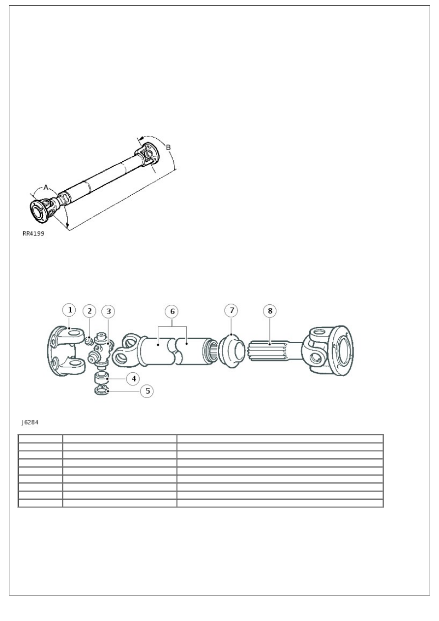
The front and rear driveshafts are 'phased', with the joints at each end, A and B mis-aligned as shown.
The phasing is necessary to allow for greater variation in angular changes. On reassembly it is essenital the driveshafts
are realigned correctly.
Item
Part Number
Description
1.
-
Flanged yoke
2.
-
Grease nipple
3.
-
Journal spider
4.
-
Needle roller bearing
5.
-
Circlip
6.
-
Splined shaft
7.
-
Rubber gaiter (dust cap)
8.
-
Ball spline shaft
Vibration Harshness
Check the propeller shaft universal joints are not seized or worn by checking for excessive radial and axial movement.
This can be done by inserting a suitable lever into the joint and checking for movement. In the event that both shafts
are satisfactory, but the vibration/harshness is still present, the transfer box operation and balance of the road wheels
should be checked.
Driveshaft - Front Driveshaft
Removal and Installation
Removal
1.
WARNING: Do not work on or under a vehicle
supported only by a jack. Always support the vehicle on safety
stands.
Raise and support the vehicle.
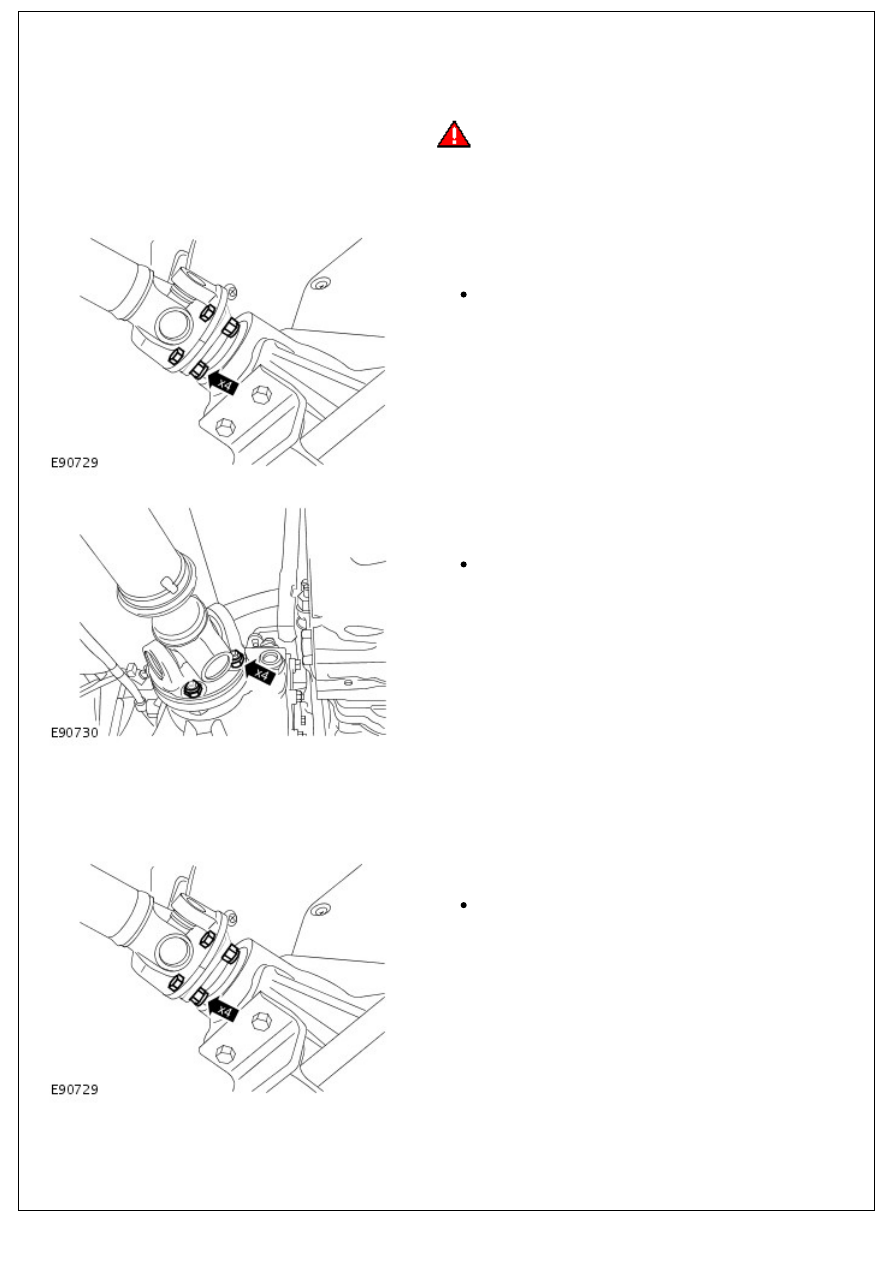
2. NOTE: Mark the front driveshaft to front differential drive
flange.
Release the driveshaft from the front differential.
Remove and discard the 4 nuts.
3. NOTE: Mark the front driveshaft to transfer case drive
flange.
Remove the driveshaft.
Remove and discard the 4 nuts.
Installation
1. NOTE: Clean the driveshaft drive flanges and mating faces.
To install, reverse the removal procedure.
2. NOTE: Install new nuts.
Tighten to 47 Nm (35 lb.ft).
Align the position of the driveshaft in relation to the
drive pinion flange.
3. NOTE: Install new nuts.
Нет комментариевНе стесняйтесь поделиться с нами вашим ценным мнением.
Текст