Defender. Manual — part 16
Front Suspension - Front Suspension
Description and Operation
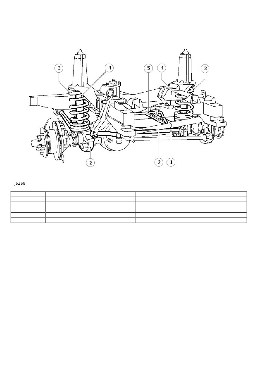
Front suspension
Item
Part Number
Description
1
-
Panhard rod
2
-
Radius arms
3
-
Coil springs
4
-
Shock absorbers
5
-
Stabilizer bar
Description
The front suspension design allows maximum wheel travel and axle articulation providing good ground clearance without
loss of traction or directional stability.
Long radius arms are fitted to the front axle and provide maximum axle articulation which is vital for off road
performance. The radius arms are secured to fabricated mounting brackets welded to the front axle. Flexible rubber
bushes are used on a stem end joint to secure the rear of the radius arms to mountings on the chassis cross member.
A Panhard rod, which ensures that the front axle remains centrally located, is fitted transversely and also uses ferrule
rubber bush mountings at both axle and chassis locations.
Two rubber bearing bushes, with retaining straps, secure the rear of the stabilizer bar to the chassis mountings, while
bushed links support the front of the bar to the front axle.
Conventional long travel coil springs and hydraulic shock absorbers are used to control body movement in all conditions.
The shock absorbers are secured to fabricated towers which are bolted to the chassis. The upper and lower fixings use a
single location stud with flexible rubber bushes, support washers and securing nuts. Retaining plates are used to secure
the coil springs to the fabricated towers and axle mountings.
Rubber bump stops are fitted underneath the chassis, adjacent to the front road springs, and prevent possible damage
that could occur should there be excessive axle to chassis movement.
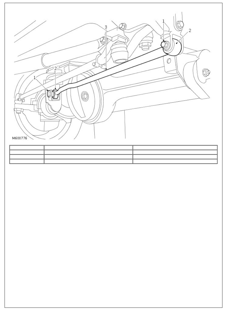
Front suspension 02MY
Item
Part Number
Description
1
-
Bolts
2
-
Bushes
3
-
Panhard rod
Changes have been incorporated to improve the durability of the suspension. The current Panhard rods are forged. New
Panhard rods are introduced which are fabricated from tubular steel and are handed.
The rods are fitted with larger bushes which use M16 bolts in place of the M14 bolts. The torque for the new bolts is
raised to 230 Nm (170 lbf.ft).
The Panhard rod support brackets are now fabricated from upgraded steel which allows the higher torque figure to be
applied to the fixing bolts.
Front Suspension - Front Stabilizer Bar
Removal and Installation
Removal
1. Mark for reassembly position of rubber bushes on stabilizer
bar.
2. Remove 4 nuts, bolts and washers securing both stabilizer
bar bush straps to chassis mounting brackets.
3. Remove nuts, bolts, washers and rubber bushes securing
stabilizer bar to both links
4. Remove stabilizer bar.
Installation
1. Position bushes on stabilizer bar. Ensure split points towards
axle on RH bush and away from axle on LH bush.
2. Instal stabilizer bar with two straps. To ensure correct fit
angled sides of bar should point down. Loosely instal the
bolts, washers and nyloc nuts.
3. Instal bolt, washers and rubber bushes. Using new nuts fit
stabilizer bar to links and tighten to 68Nm (50 lbf.ft).
4. Tighten nuts securing straps to 30Nm (22lbf.ft).
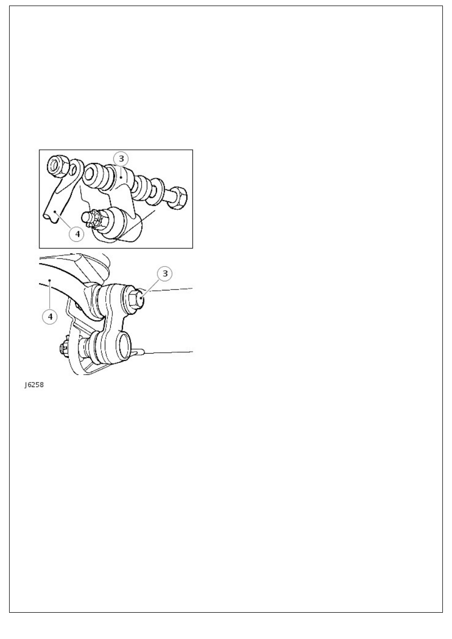
Front Suspension - Front Stabilizer Bar Link
Removal and Installation
Removal
1. Raise vehicle on ramp.
2. Remove 2 nuts, bolts, washers and rubber bushes from ball
joint links.
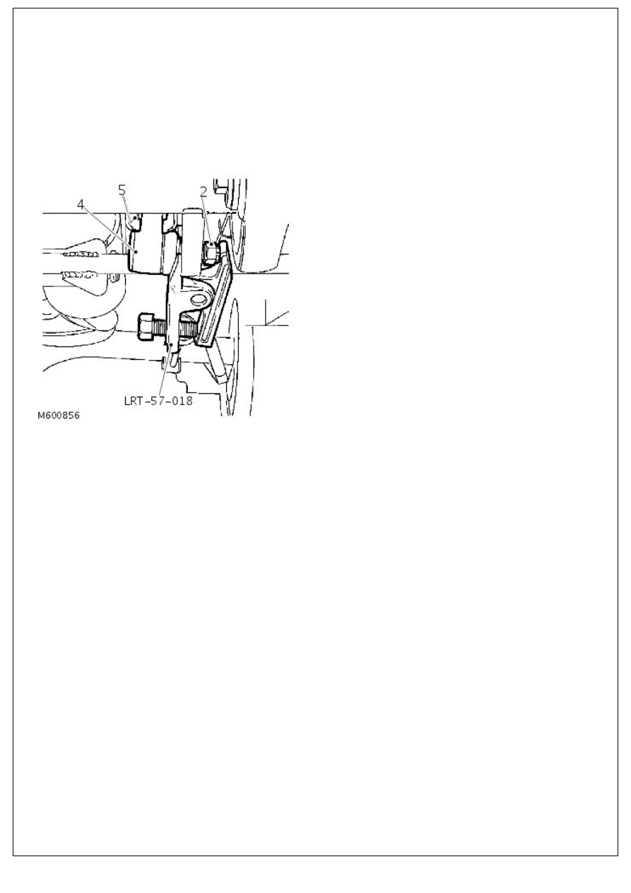
3. Remove cotter pin and loosen castellated nut a few turns.
4. Release link joint using tool LRT-57-018 as shown.
5. Remove castellated nut and link.
Installation
1. Fit link and castellated nut. Ensure ball joint link arm points
up. Tighten nut to 40 Nm (30 lbf/ft) and fit new cotter pin.
2. Align stabilizer bar to links.
3. Fit bolts, washers and rubber bushes using new self locking
nuts and secure stabilizer bar to links. Tighten fixings to 68
Nm (50 lbf/ft).
4. Lower vehicle.
Нет комментариевНе стесняйтесь поделиться с нами вашим ценным мнением.
Текст