Defender. Manual — part 17
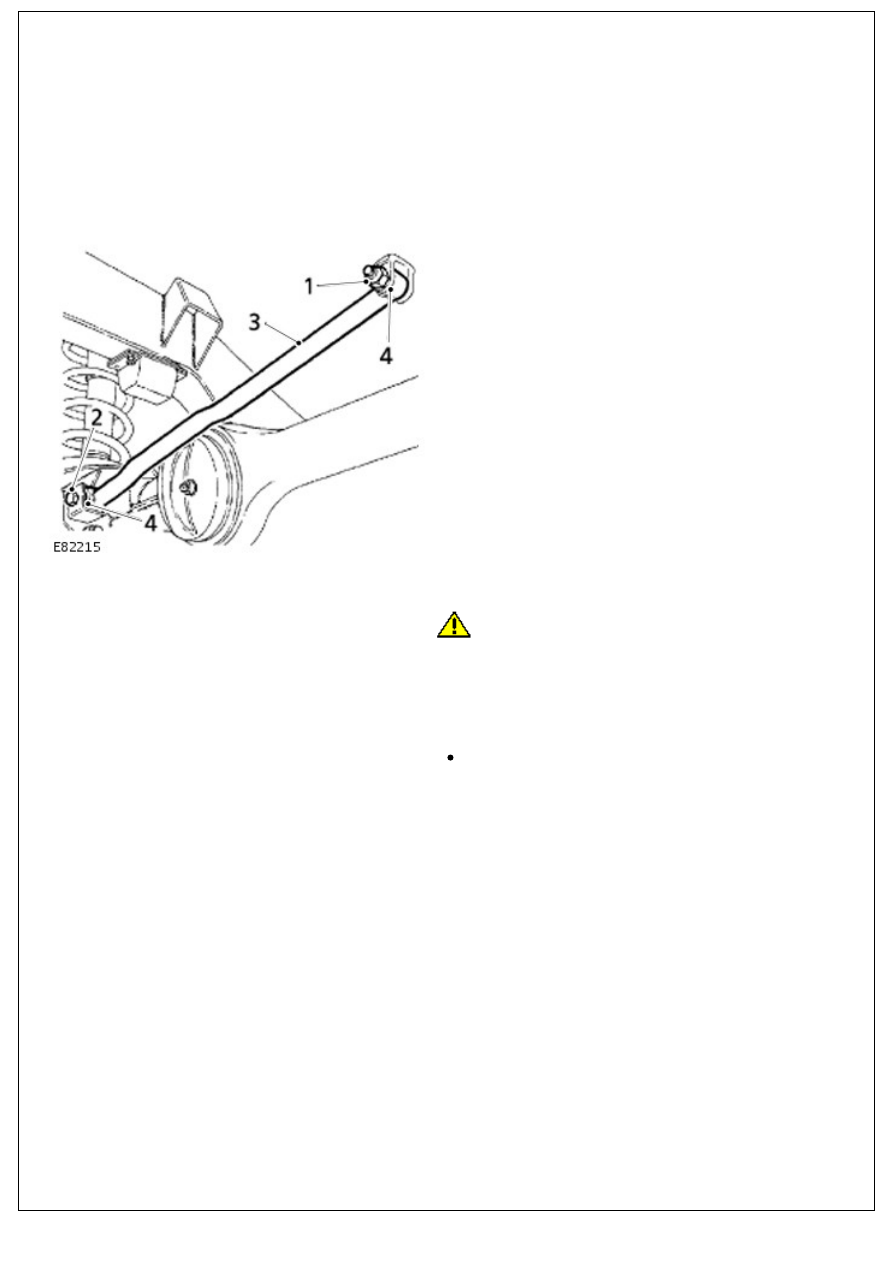
Front Suspension - Panhard Rod
Removal and Installation
Removal
1. Remove fixings at mounting arm.
2. Remove fixings at axle bracket.
3. Remove panhard rod.
4. Using a suitable length of steel tubing, press out flexible
bushes. Ensure tubing locates on outer edge of bush and
not on rubber inner.
Installation
1.
CAUTION: Apply pressure to outer edge of bush, and
not rubber inner.
Install replacement bushes.
2. Install panhard rod to axle bracket and mounting arm.
Tighten chassis fixing (1) to 200 Nm (148 lbf.ft). Tighten axle
fixing (2) to 250 Nm (184 lbf.ft).
Note: If you are re-using fixings on a vehicle built prior
to VIN 735937, then tighten the axle fitting to 250 Nm
(184 lbf.ft) and the chassis fixing to 230 Nm (170 lbf.ft).
If a new fixing is used on any vehicle, then use the
torque settings of 200 Nm and 250 Nm, respectively.
Front Suspension - Spring
Removal and Installation
Removal
1. Remove front shock absorber.
For additional information, refer to:
Front Shock Absorber
(204-01 Front Suspension, Removal and Installation).
CAUTION: Avoid over stretching brake hoses. If necessary, loosen hose connector locknuts to allow hoses to follow
axle.
2. Lower axle sufficient to free road spring.
3. Withdraw road spring.
4. Withdraw shock absorber bracket securing ring.
Installation
1. Install shock absorber bracket retaining ring. Retain in
position with a nut.
2. Position road spring and raise axle.
3. Remove nut retaining securing ring.
4. Install front shock absorber.
For additional information, refer to:
Front Shock Absorber
(204-01 Front Suspension, Removal and Installation).
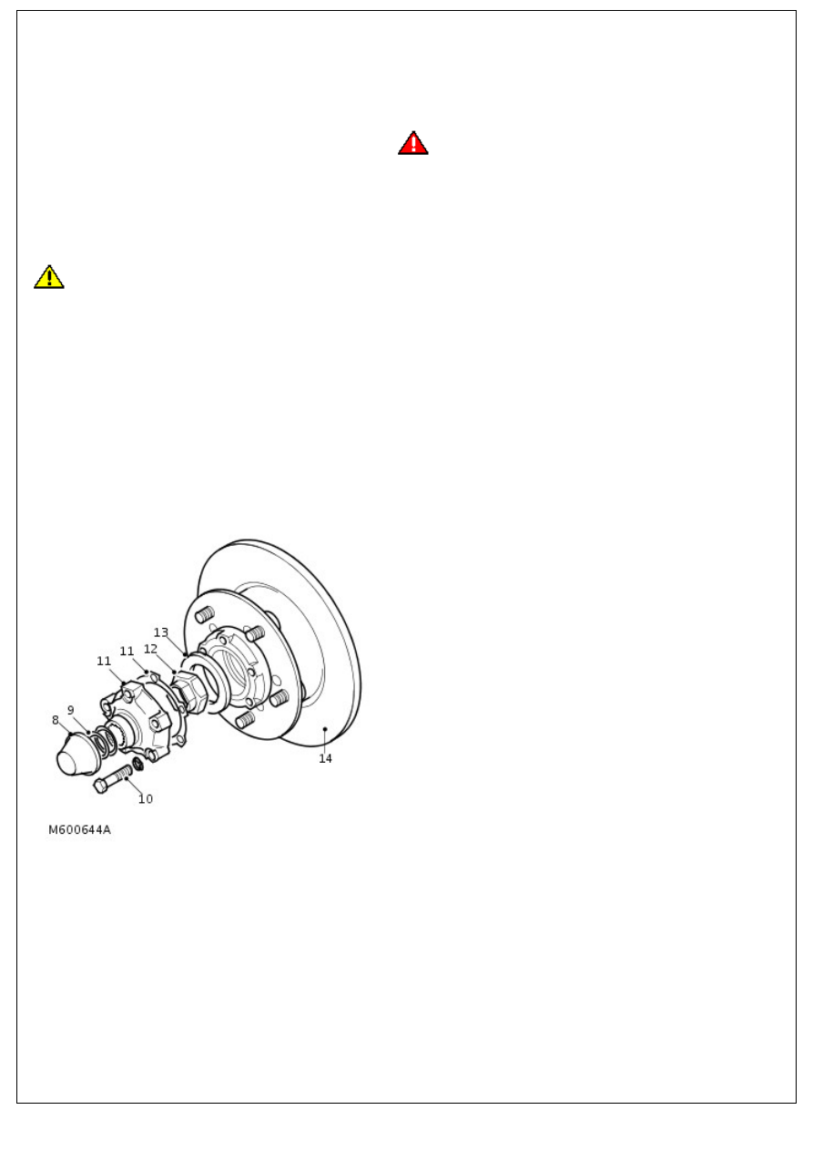
Front Suspension - Front Wheel Bearing and Wheel Hub
Removal and Installation
Removal
1. Raise front of vehicle.
2.
WARNING: Support on safety stands.
Remove front road wheel.
3. Pull back front brake caliper jump hose shield and clamp
brake hose.
4. Position container collect brake fluid.
5. Loosen brake pipe to jump hose union and disconnect.
CAUTION: Use 2 spanners when loosening or tightening unions.
6. Remove 2 bolts securing brake caliper to hub.
7. Remove brake caliper.
8. Remove dust cap.
9. Remove circlip and shim(s) from drive shaft.
10. Remove and discard 5 bolts securing driving member to
hub.
11. Remove driving member and discard gasket.
12. Knock back staking and using a suitable socket, remove
and discard hub nut.
13. Remove washer from hub.
14. Remove hub and brake disc assembly complete with
bearings.
15. Remove outer bearing and spacer from hub.
16. Remove grease seal and inner bearing from hub.
17. Remove inner and outer bearing tracks from hub.
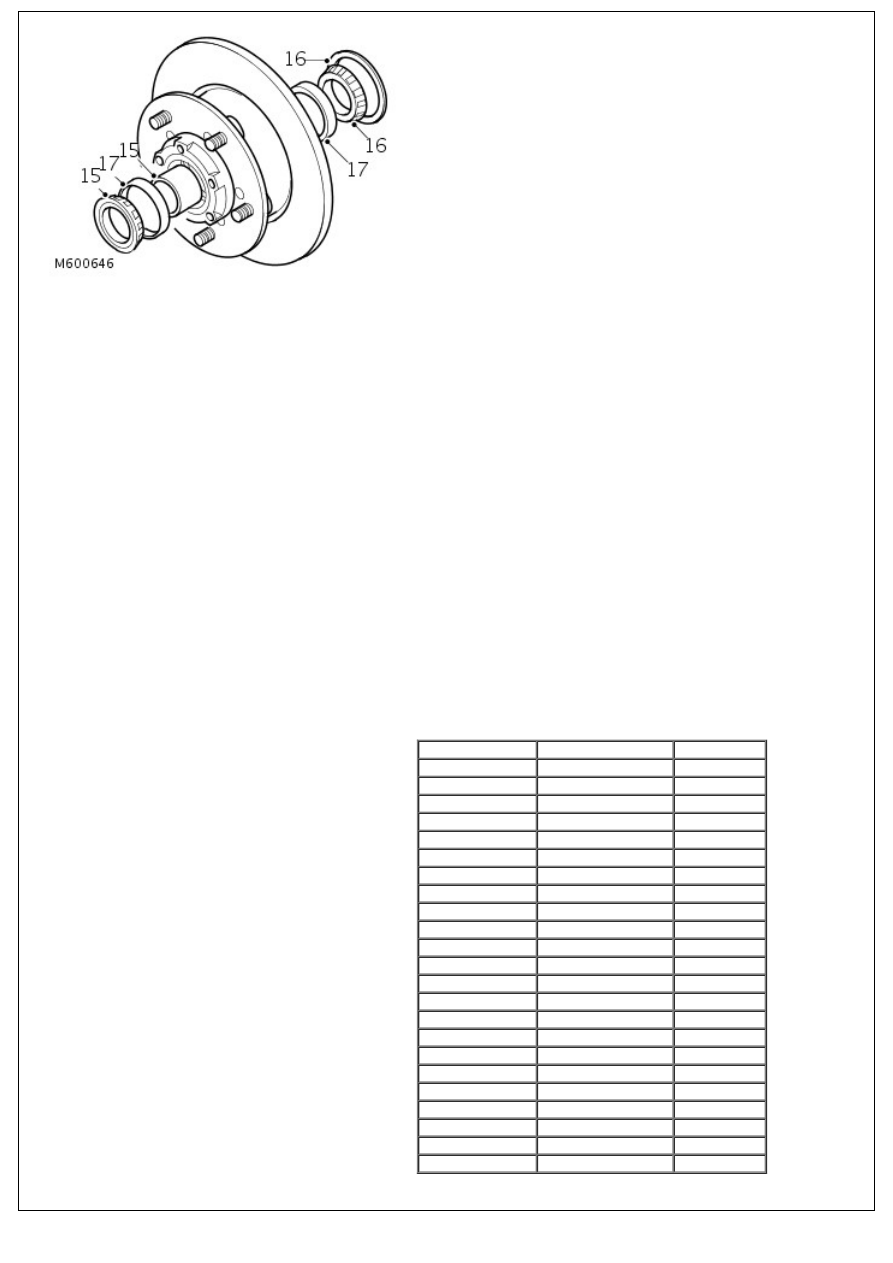
17. Remove inner and outer bearing tracks from hub.
Installation
1. Clean hub and bearing locations.
2. Instal inner and outer bearing tracks to hub.
3. Pack inner bearing with grease and fit to hub.
4. Instal new seal flush with rear face of hub using LRT-54-003
and LRT-99-003.
5. Clean stub axle.
6. Pack outer bearing with grease, fit spacer and bearing to
hub.
7. Position LRT-54-019 over hub nut threads on axle casing.
8. Instal hub assembly to stub axle, remove LRT-54-019.
9. Instal washer and new hub nut and tighten to 30 Nm (22
lbf.ft).
10. Rotate and push/pull hub to settle bearings. Tighten hub
nut to 210 Nm (150 lbf.ft).
11. To check hub assembly end float, mount a dial gauge using
bracket LRT-99-503 to driving member bolt hole.
12. Ensure dial gauge is contacting hub nut face.
13. Move hub assembly in and out noting dial gauge reading.
14. If end float is present refer to table for correct spacer and
change spacer as necessary.
End float (mm) Spacer size (mm) Colour code
0.00
15.5
Purple
0.025
15.4
Yellow
0.050
15.4
Yellow
0.075
15.4
Yellow
0.10
15.3
Red
0.125
15.3
Red
0.150
15.3
Red
0.175
15.2
Blue
0.200
15.2
Blue
0.225
15.2
Blue
0.250
15.2
Blue
0.275
15.1
Green
0.300
15.1
Green
0.325
15.1
Green
0.350
15.1
Green
0.375
15.0
Black
0.400
15.0
Black
0.425
15.0
Black
0.450
15.0
Black
0.475
14.9
White
0.500
14.9
White
0.525
14.9
White
0.550
14.9
White
15. When no end float is evident, remove the dial gauge and
Нет комментариевНе стесняйтесь поделиться с нами вашим ценным мнением.
Текст