Defender. Manual — part 15
!
"!
2: Chassis
!
!
!
Suspension System - General Information -
Suspension
90
Front
Live beam axle, linear rate coil springs, coaxial telescopic nitrogen-charged hydraulic shock absorbers.
Lateral axle location by fabricated steel Panhard rod and longitudinal axle location by forged steel radius
arms. Stabilizer bar if alloy wheels fitted.
Rear
Live beam axle, linear rate coil springs (dual rate for heavy duty derivative), telescopic nitrogen-charged
hydraulic shock absorbers. Lateral axle location by forged steel 'A' frame arms and longitudinal axle
location by fabricated steel trailing links. Stabilizer bar if alloy wheels fitted.
110
Front
Live beam axle, dual rate coil springs, coaxial telescopic nitrogen-charged hydraulic shock absorbers.
Lateral axle location by fabricated steel Panhard rod and longitudinal axle location by forged steel radius
arms. Stabilizer bar if station wagon or crew cab derivative.
Rear
Live beam axle, triple rate coil springs, telescopic nitrogen-charged hydraulic shock absorbers. Lateral axle
location by forged steel 'A' frame arms and longitudinal axle location by fabricated steel trailing links.
Stabilizer bar if station wagon or crew cab derivative.
110 heavy
duty and
130
Front
Live beam axle, linear rate coil springs, coaxial telescopic nitrogen-charged hydraulic shock absorbers.
Lateral axle location by fabricated steel Panhard rod and longitudinal axle location by forged steel radius
arms. Stabilizer bar.
Rear
Live beam axle, triple rate coil springs, coaxial linear rate helper springs, telescopic nitrogen-charged
hydraulic shock absorbers. Lateral axle location by forged steel 'A' frame arms and longitudinal axle
location by fabricated steel trailing links. Stabilizer bar.
Road spring data
Road spring
Part number
Colour code
90 2 seat utility (2400 Kg)
Front - Driver's side
REB500200
Red/green/white
Front - Passenger side
REB500220
Red/green/orange
Rear - Driver's side
NRC 9448
Blue/red
Rear - Passenger side
NRC 9449
Yellow/white
90 2 seat utility (2550 Kg)
Front - Driver's side
REB500200
Red/green/white
Front - Passenger side
REB500220
Red/green/orange
Rear - Driver's side
RKB101230
Green/yellow/red
Rear - Passenger side
RKB101240
Green/yellow/white
90 4 seat station wagon (2400 Kg)
Front - Driver's side
REB500200
Red/green/white
Front - Passenger side
REB500220
Red/green/orange
Rear - Driver's side
RKB500290
Red/green/green
Rear - Passenger side
RKB500280
Red/green/red
90 4 seat station wagon (2550 Kg)
Front - Driver's side
REB500200
Red/green/white
Front - Passenger side
REB500220
Red/green/orange
Rear - Driver's side
RKB500270
White/green/pink
Rear - Passenger side
RKB500310
White/green/purple
LHD 110 2 seat utility, 5 seat station wagon and 5 seat crew cab (3050 Kg)
Front - Driver's side
NRC 8044
White/white
Front - Passenger side
NRC 8045
Yellow/yellow
Rear - Both sides
RKB101111
Purple/brown
RHD 110 2 seat utility, 5 seat station wagon and 5 seat crew cab (3050 Kg)
Front - Both sides
NRC 8045
Yellow/yellow
Rear - Both sides
RKB101111
Purple/brown
LHD 110 7 seat station wagon (3050 Kg)
Front - Driver's side
NRC 8044
White/white
Front - Passenger side
NRC 8045
Yellow/yellow
Rear - Both sides
RKB500300
White/green/green
RHD 110 7 seat station wagon (3050 Kg)
Front - Both sides
NRC 8045
Yellow/yellow
Rear - Both sides
RKB500300
White/green/green
110 heavy duty and all 130 (3500Kg)
Front - Driver's side
NRC 9448
Blue/red
Front - Passenger side
NRC 9449
Yellow/white
Rear - Both sides
RKB101111
Purple/brown
Rear helper springs - Both sides
RRC 3266
No colour code
Torque values - front suspension
Nm
Drag link ball joint nut
40 + tighten to next castle slot on nut
Tie rod ball joint nut
40 + tighten to next castle slot on nut
Securing ring for mounting turret
14
Panhard rod to axle
230
Panhard rod to chassis bracket
230
Panhard rod chassis bracket to chassis
123
Radius arm to axle
210
Radius arm to chassis
176
Shock absorber (upper and lower mountings)
38
Bump stop to chassis frame
22
Stabilizer bar to stabilizer link
75
Stabilizer link to axle
40 + tighten to next castle slot on nut
Stabilizer bar to chassis bracket
45
Tie bar to Panhard rod mounting bracket
85
Tie bar to steering box
85
Torque values - Rear suspension
Nm
Trailing link to chassis bush
176
Trailing link to chassis
62
Trailing link to axle
176
'A' frame ball joint to axle
176
'A' frame to ball joint
115
'A' frame to chassis bracket
Vehicles fitted with ! inch UNF bolts
176
Vehicles fitted with M16 bolts
150
'A' frame to chassis bracket to chassis (if applicable)
63
Shock absorber to axle
38
Shock absorber to shock absorber upper mounting bracket
75
Shock absorber upper mounting bracket to chassis
44
Stabilizer bar to stabilizer link
75
Stabilizer link to axle
40 + tighten to next castle slot on nut
Stabilizer bar bush bracket to chassis
22
Bump stop to chassis frame
22
Suspension System - General Information - Front Toe Adjustment
General Procedures
• NOTE: Recognised front wheel alignment and tracking equipment should be used for this operation. Only the use of
basic equipment is described below. No adjustment is provided for castor, camber or swivel pin inclinations.
1. Set vehicle on level ground with road wheels positioned
straight ahead.
2. Push vehicle back and forwards to settle linkage.
3. Set up the equipment to manufacturers instructions and
check alignment as advised by equipment supplier.
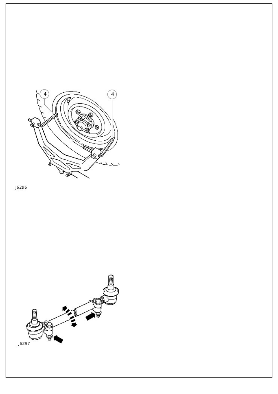
4. Position trammel probes on inner face of wheel, not the
rims, if the latter are damaged.
5. Measure toe-out at horizontal centre-line of wheels.
6. Check tightness of clamp bolt fixings. Tighten to 14 Nm
(10lbf/ft).
7. Slacken clamps at both ends of track rod.
8. Rotate track rod to increase or decrease its effective length
until correct toe-out is obtained.
For additional information, refer to:
Specifications
(211-00
Steering System - General Information, Specifications).
9. Push vehicle rearwards turning steering wheel from side to
side to settle ball joints. With road wheels set in straight
ahead position, push vehicle forward a short distance.
10. Recheck track and adjust if necessary.
11. When alignment is correct, tap ball joints in direction of
arrows to maximum of travel, to ensure full unrestricted
movement of track rod.
12. Tighten clamp bolts to 14 Nm (10 lbf/ft).
Нет комментариевНе стесняйтесь поделиться с нами вашим ценным мнением.
Текст