Defender. Manual — part 170

Manual Transmission/Transaxle - Synchronizers
Disassembly and Assembly of Subassemblies
Disassembly
1. NOTE: Make a note of/mark the installed positions of the
components before removal.
1. Sliding collar.
2. Sliding block assemblies.
3. Synchronizer hub.
Assembly
1. NOTE: Make sure that the components are installed in their
original positions.
To install, reverse the removal procedure.
Manual Transmission/Transaxle - Transmission
Assembly
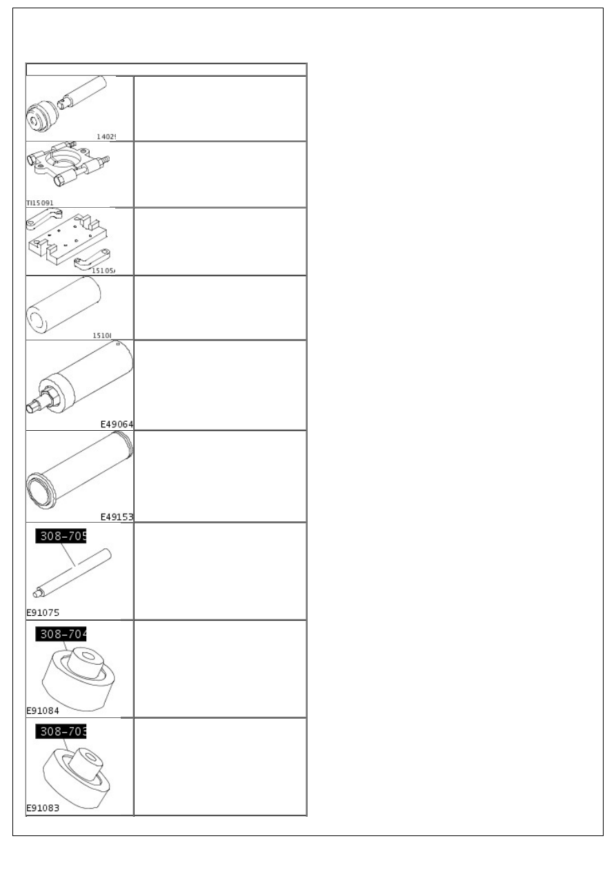
Special Tool(s)
Installer, Front Wheel Hub Bearing
Cup/Seal
204-087
Remover, Bearing/Gear
205-310
Mounting Bracket,
Engine/Differential
205-329
Protector, Axle Shaft
205-332
Installer, Output Drive Flange Seal
308-604
Installer, Input Shaft Seal
308-605
Handle, Bearing Installer
308-705
Installer, Countershaft Bearing
308-704
Installer, Input Shaft Bearing
308-703
Name
Transmission Fluid
High-Temperature Grease
Gasket Eliminator Sealant
Adhesive - Loctite 243
Installer, Output Shaft Bearing
308-702
Installer, Selector Shaft Seal
308-700
General Equipment
Tie Straps
Hot air gun
Hydraulic press
Materials
Specification
WSD-M2C200-C
ESD-M1C220-A
WSK-M2G348-A5
WSK-M2G349-A7
Assembly
1. NOTE: All synchronizer rings and needle bearings should be
lubricated with clean transmission fluid prior to assembly.
transmission fluid
2. Install the 4th gear and 3rd/4th gear synchronizer assembly
onto the countershaft.
3. Install the 3rd/4th gear synchronizer assembly snap ring
onto the countershaft.
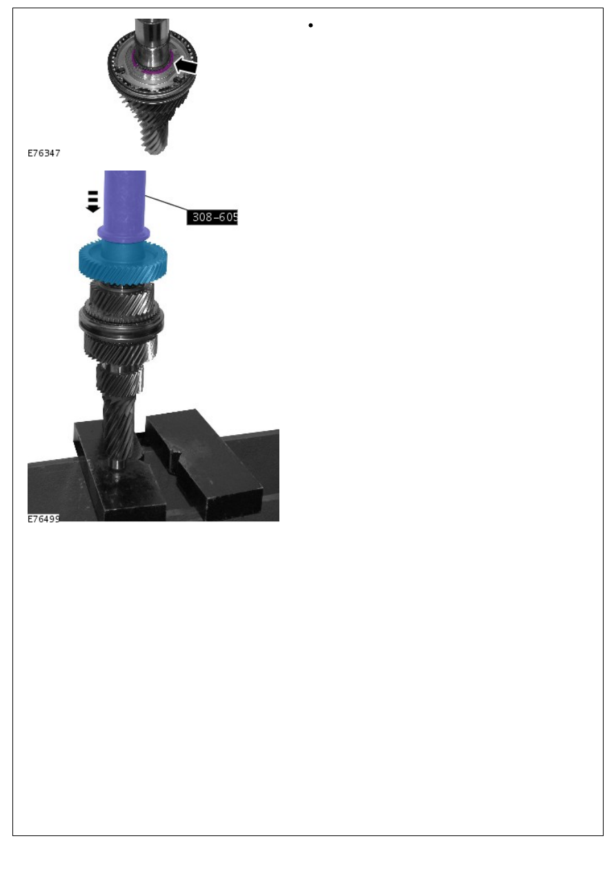
Install a new snap ring.
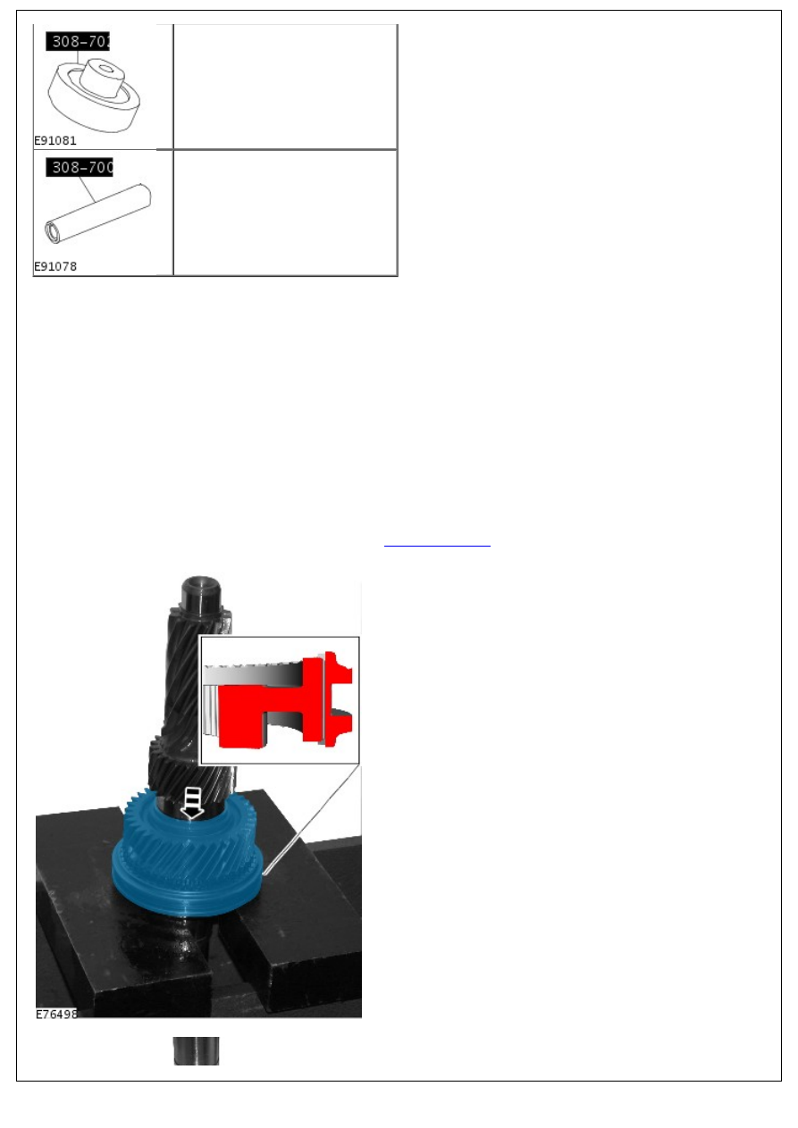
4. Using the special tool, install the 6th gear onto the
countershaft.
5. Using the special tool, install the 5th gear.
Нет комментариевНе стесняйтесь поделиться с нами вашим ценным мнением.
Текст