Defender 300Tdi (1996+). Manual — part 81

76
CHASSIS AND BODY
8
REPAIR
11. Remove 2 self-tapping screws from each side
and remove glass lower channels.
12. Remove inner and outer weather strips from
door sill.
13. Lower glass down to bottom of door, lift glass
over lower edge and withdraw from door.
14. Remove lift channel from glass, if necessary.
Refit
15. Fit lift channel to new glass, if necessary.
16. Insert glass into lower channels and carefully
push glass up to top of frame.
17. Secure lower channels with 4 self-tapping
screws. Ensure that screw heads are screwed
down firmly below bottom of channels to prevent
damage to glass.
18. Fit door check rod and bend end stop back to
closed position.
19. Fit check stop torsion bar and secure with 2 nuts
and bolts.
20. Fit water channel and secure with single
self-tapping screw.
21. Fit mounting panel complete with rods and
remote control lever.
22. Connect control rods to latch and door outer
handle mechanism.
23. Fit door sill locking button and connect control
rod
See Sill locking button .
24. Fit window regulator
See Window regulator .
25. Fit door inner and outer sill wear strips.
26. Fit and re-seal plastic sheet.
27. Fit door trim casing
See Door trim casing .
28. Connect door check rod to door post.
CHASSIS AND BODY
9
REPAIR
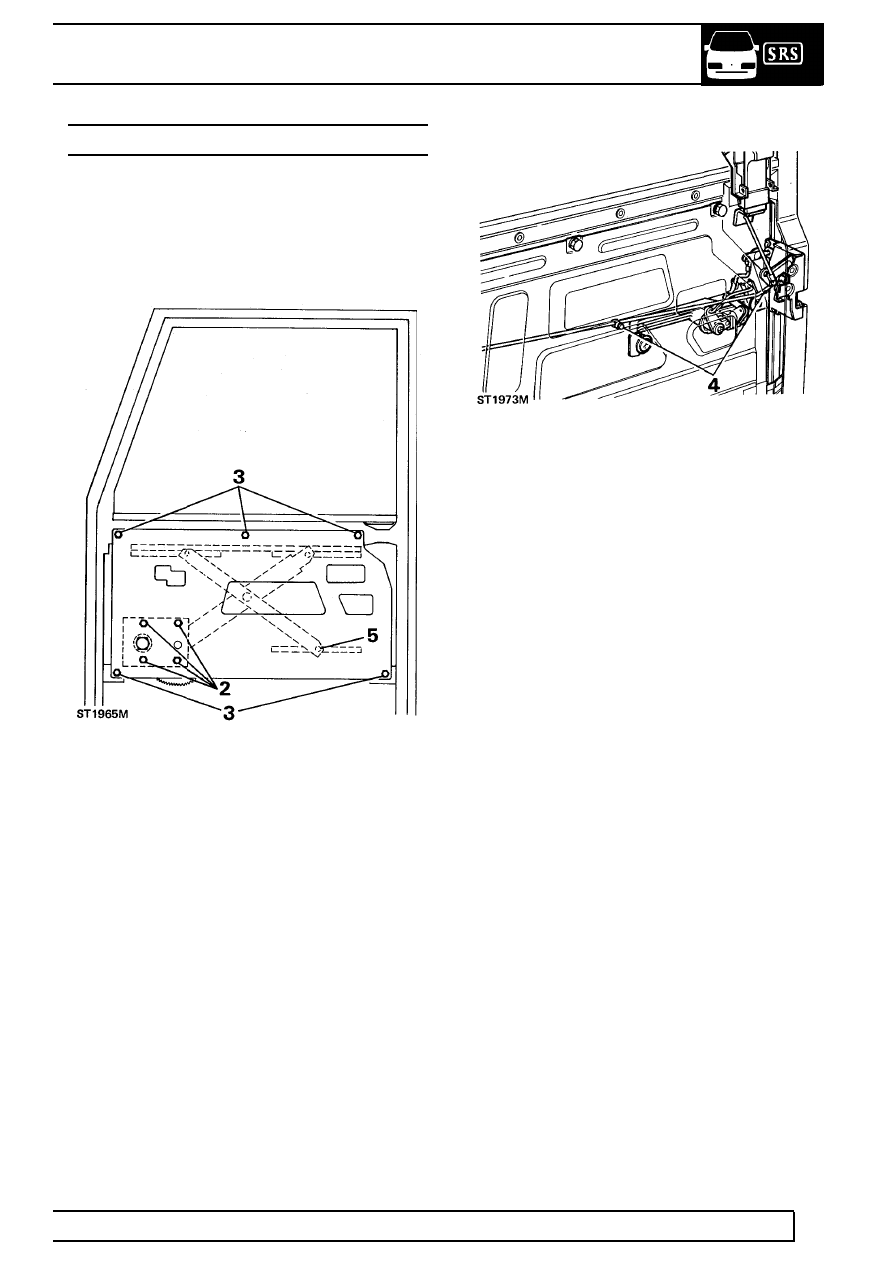
MOUNTING PANEL - FRONT DOOR
Service repair no - 76.11.28
Remove
1. Remove door trim casing
See Door trim
casing and plastic sheet.
2. Remove 4 screws securing window regulator to
mounting panel.
3. Remove 5 screws securing mounting panel to
door frame.
4. Release remote control lever rod from latch
mechanism and from plastic clip in mounting
panel.
5. Slide window regulator arm from mounting panel
channel and remove panel with remote control
lever and rod.
Refit
6. Engage window regulator arm in mounting panel
channel.
7. Connect remote control rod to latch mechanism
and secure with clip.
8. Fit mounting panel and retain with 5 screws.
9. Secure window regulator to mounting panel with
4 screws.
10. Raise and lower window to check for free
movement.
11. Fit plastic sheet, and door trim casing
See
Door trim casing .

76
CHASSIS AND BODY
10
REPAIR
SILL LOCKING BUTTON - FRONT DOOR
Service repair no - 76.37.29
Remove
1. Remove door trim casing
See Door trim
casing .
2. Peel back sufficient of plastic sheet to expose
mechanism.
3. Release spring clip and disconnect operating rod
from latch mechanism.
4. Remove 2 screws and withdraw locking button
assembly.
Refit
5. Secure locking button assembly to door with 2
screws.
6. Connect operating rod to latch mechanism and
secure with spring clip.
7. Re-seal plastic sheet and fit door trim casing
See Door trim casing .
WINDOW REGULATOR - FRONT DOOR
Service repair no - 76.31.45
Remove
1. Remove door trim casing
See Door trim casing
.
2. Remove plastic sheet.
3. Temporarily fit handle, position window half open
and support with a length of timber.
4. Remove 2 lower screws securing mounting
panel to door and slacken 3 upper screws.
5. Remove 4 screws retaining window regulator to
mounting panel and slide operating arms from
channels attached to glass and mounting panel
and remove regulator.
Refit
6. Insert regulator operating arms into channels.
7. Fit and tighten mounting panel lower screws and
tighten upper screws.
8. Position holes in regulator to line-up with holes in
mounting panel and secure with 4 screws.
9. Temporarily fit regulator handle and check that
glass can be raised and lowered without tight
spots.
10. Secure plastic sheet.
11. Fit door trim casing
See Door trim casing .

CHASSIS AND BODY
11
REPAIR
REMOTE CONTROL LEVER - FRONT DOOR
Service repair no - 76.37.31
Remove
1. Remove door trim casing
See Door trim
casing .
2. Peel back sufficient of plastic sheet to gain
access to remote lever.
3. Release spring clip and disconnect control rod
from latch mechanism.
4. Release control rod from plastic clip in mounting
panel.
5. Remove 2 screws securing remote control lever
to mounting panel and withdraw lever and
control rod.
Refit
6. Feed control rod into position and loosely secure
lever to mounting panel with 2 screws.
7. Connect control rod to latch mechanism and
secure with spring clip.
8. Tighten control lever retaining screws.
9. Secure control rod to plastic clip in mounting
panel.
10. Secure plastic sheet.
11. Fit door trim casing
See Door trim casing .
Нет комментариевНе стесняйтесь поделиться с нами вашим ценным мнением.
Текст