Defender 300Tdi (1996+). Manual — part 80

76
CHASSIS AND BODY
4
REPAIR
Refit
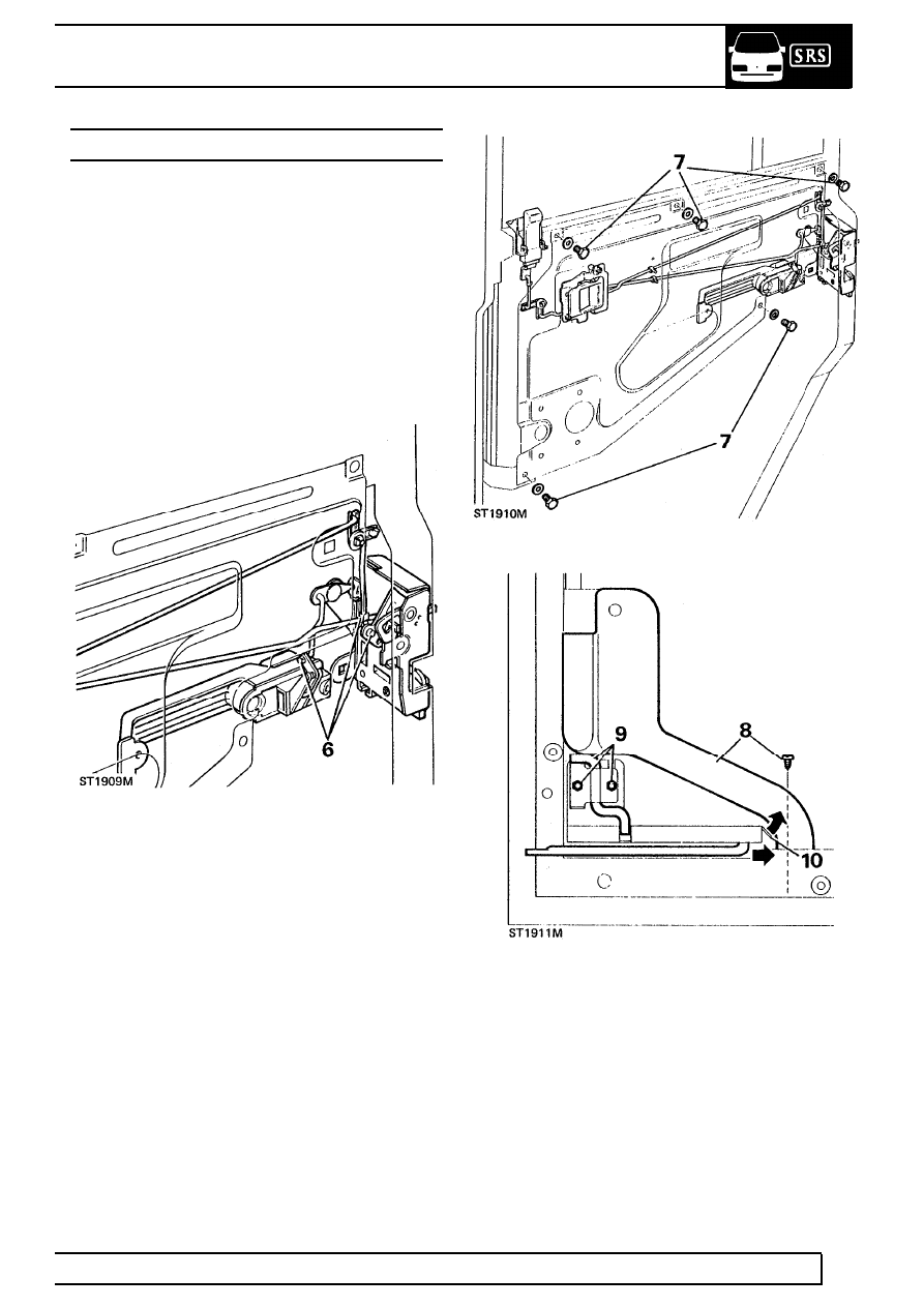
5. Insert lifting arm button into lifting channel.
6. Position regulator so that fixing holes line-up with
holes in mounting panel.
7. Secure with 4 screws and tighten evenly.
8. Temporarily fit handle and check that glass can
be raised and lowered smoothly without tight
spots.
9. Fit plastic sheet.
10. Fit door trim
See Door trim casing .
EXTERIOR HANDLE - REAR SIDE DOOR
Service repair no - 76.58.02
Remove
1. Remove door trim casing
See Door trim casing
.
2. Peel back sufficient of plastic sheet to gain
access to handle mechanism.
3. Disconnect actuating rod from handle operating
lever.
4. Remove 2 screws and withdraw handle and
bezels.
Refit
5. Fit handle to door ensuring that both bezels are
in position - flat faces towards door and secure
with 2 screws.
6. Connect actuating rod to handle operating lever
and secure with spring clip.
7. Re-seal plastic sheet.
8. Fit door trim casing
See Door trim casing .

CHASSIS AND BODY
5
REPAIR
SILL LOCKING BUTTON - REAR SIDE DOOR
Service repair no - 76.37.30
Remove
1. Remove door trim casing
See Door trim casing
.
2. Peel back sufficient of plastic sheet to reveal
mechanism.
3. Release spring clip securing button to operating
rod and withdraw rod from button.
4. Remove 2 screws securing button to door panel
and remove button.
Refit
5. Secure locking button assembly to door panel
with 2 screws.
6. Fit operating rod to button assembly and secure
with spring clip.
7. Re-seal plastic sheet and fit door trim casing
See Door trim casing .
REMOTE CONTROL LEVER - REAR SIDE DOOR
Service repair no - 76.37.32
Remove
1. Remove door trim casing
See Door trim casing
.
2. Peel-back sufficient of plastic sheet to gain
access to remote lever.
3. Remove spring clip and disconnect control rod
from locking button.
4. Release spring clip and disconnect short locking
button control rod from latch mechanism.
5. Disconnect long remote control rod from latch
assembly.

76
CHASSIS AND BODY
6
REPAIR
6. Remove 2 screws securing remote control lever
to mounting panel.
7. Release control rods from plastic retaining clips
located in mounting panel.
8. Withdraw remote control lever and rods from
door.
Refit
9. Fit plastic retaining clips to rod assembly into
position and secure with 2 screws.
10. Connect control rods to latch assembly and
secure with clips.
11. Fit plastic retaining rod clips to mounting panel.
12. Connect control rod to locking button and secure
with clip.
13. Re-seal plastic sheet and fit door trim casing
See Door trim casing .
DOOR LATCH - REAR SIDE DOOR
Service repair no - 76.37.13.
Remove
1. Remove door trim casing
See Door trim
casing .
2. Peel-back sufficient of plastic sheet to reveal
latch.
3. Release remote control lever rod from latch
assembly.
4. Disconnect door outer handle control rod from
latch assembly.
5. Disconnect door locking button remote control
rod from latch mechanism.
6. Remove 3 retaining screws and withdraw latch
assembly from door.
Refit
7. Fit latch assembly to door and secure with 3
screws, noting that uppermost screw is longer.
8. Connect remote control levers to latch
mechanism reversing instructions 3, 4 and 5.
9. Re-seal plastic sheet and fit door trim casing
See Door trim casing .
CHASSIS AND BODY
7
REPAIR
DOOR GLASS - REAR SIDE DOOR
Service repair no - 76.31.02
Remove
1. Disconnect door check rod from door post.
2. Remove door trim casing
See Door trim casing
.
3. Remove plastic sheet.
4. Remove window regulator assembly
See
Window regulator - rear side door .
5. Disconnect and remove door sill locking button
See Sill locking button .
6. Disconnect control rods from latch and door
outer handle mechanism.
7. Remove 4 screws retaining mounting panel to
door and remove panel, complete with rods and
control lever.
8. Remove single self tapping screw to remove
water channel.
9. Remove 2 screws and remove door check
torsion bar.
10. Remove door check rod by bending back end
stop to enable rod to be withdrawn.
Нет комментариевНе стесняйтесь поделиться с нами вашим ценным мнением.
Текст