Defender 300Tdi (1996+). Manual — part 90
80
HEATING AND VENTILATION
2
REPAIR
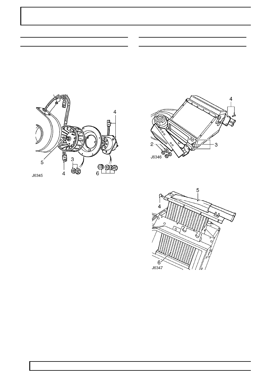
BLOWER MOTOR
Service repair no - 80.20.15
Remove
1. Remove heater unit
See Heater unit .
2. Remove 3 nuts securing angled bracket to
heater unit. Pivot bracket to remove from studs.
3. Remove 5 nuts securing blower motor assembly
to volute housing.
4. Disconnect harness connector and remove
blower motor from volute housing.
5. Release circlip and withdraw impeller from motor
shaft.
6. Remove 3 nuts securing blower motor to
mounting plate.
7. Remove blower motor.
8. Examine components for signs of wear and
renew as necessary.
Refit
9. Apply Bostik 1261 adhesive to mating faces of
mounting plate and blower motor.
10. Fit blower motor to mounting plate and secure
with 3 nuts. Ensure rubber mountings are
correctly fitted.
11. Fit impeller to motor shaft and secure with circlip.
12. Position blower motor assembly in volute
housing and secure with 5 nuts. Fit angled
bracket to lower fixing.
13. Reconnect harness plug to resistor harness and
fit angled bracket to heater unit.
14. Fit heater unit
See Heater unit .
HEATER MATRIX
Service repair no - 80.20.29
Remove
1. Remove heater unit
See Heater unit .
2. Remove 2 nuts securing angled bracket to
heater unit. Pivot bracket to remove from studs.
3. Remove 14 screws and detach two matrix
retaining plates from heater unit base.
4. Remove 9 screws securing matrix top retaining
plate.
5. Withdraw heater matrix through top of heater
unit casing.
HEATING AND VENTILATION
3
REPAIR
Refit
6. Fit foam rubber to heater matrix casing.
7. Position matrix in heater unit casing.
8. Check that both vent flaps operate correctly
without sticking.
9. Secure matrix top retaining plate.
10. Secure matrix bottom retaining plates.
11. Fit heater unit
See Heater unit .
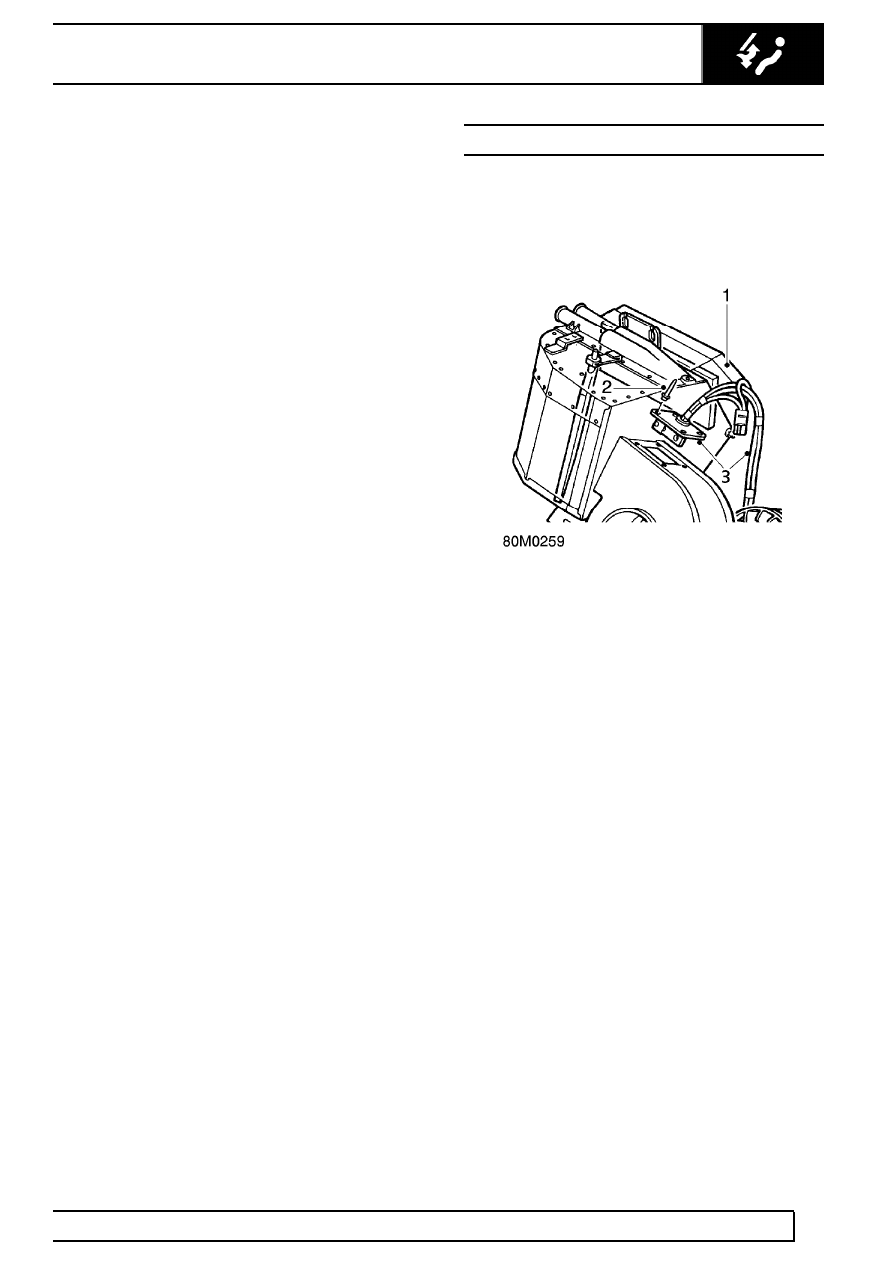
RESISTOR UNIT
Service repair no - 80.20.17
Remove
1. Remove heater unit
See Heater unit .
2. Drill out 4 rivets securing resistor mounting plate
to top of volute housing.
3. Remove resistor and disconnect blower motor
plug from harness.
Refit
4. Apply Bostik adhesive to resistor mounting plate
and rivet to volute housing.
5. Reconnect blower harness motor plug.
6. Fit heater unit
See Heater unit .
80
HEATING AND VENTILATION
4
REPAIR
HEATER CONTROL CABLE - TEMPERATURE
CONTROL
Service repair no - 80.10.05
Remove
1. Disconnect battery.
2. Remove 4 screws securing instrument panel to
fascia cowl.
3. Pull instrument panel away from fascia and
disconnect speedometer cable to give easier
access to control cable at bulkhead.
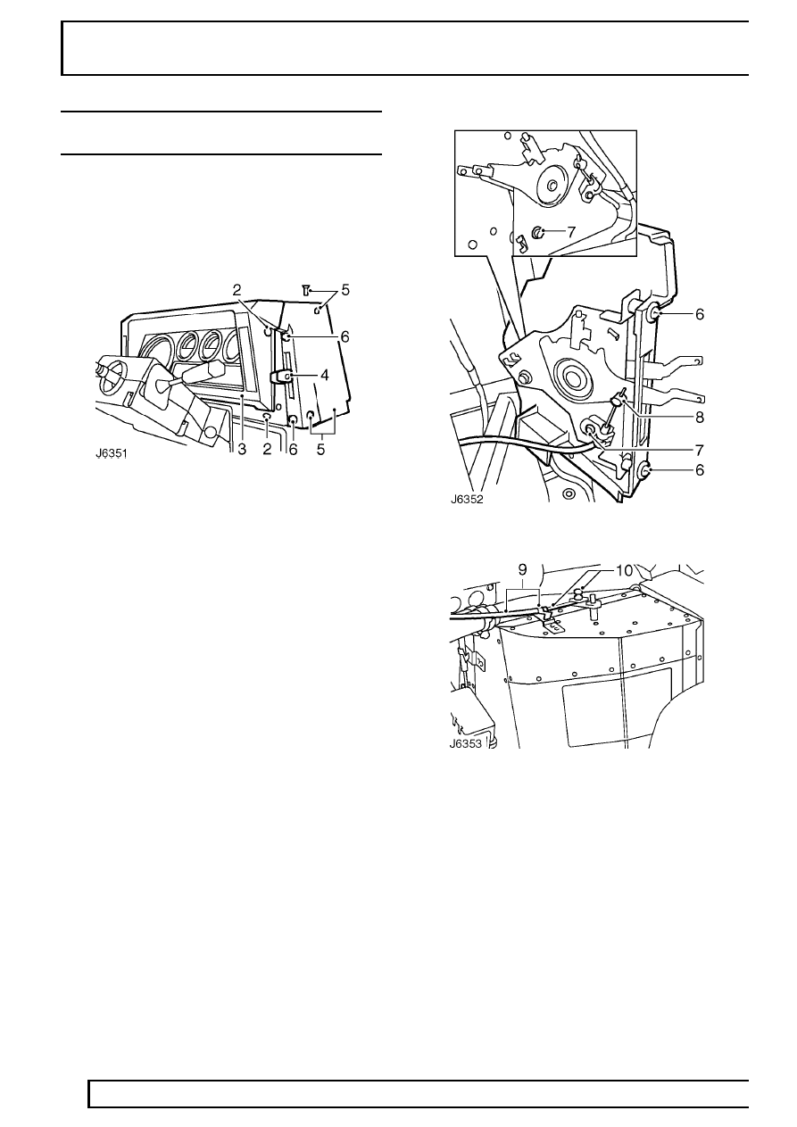
4. Remove retaining screws and pull off air
distribution and temperature control lever knobs.
5. Remove 3 screws and detach side cover,
complete with control lever assembly.
6. Remove 2 screws securing control lever
assembly to side cover and remove cover. Note
plastic screw spacers fitted between cover and
control lever assembly and retain.
7. Remove small bolt and release outer cable
retaining clip.
8. Slacken grub screw and release inner cable from
clevis.
9. From inside engine compartment, release outer
cable retaining clip at heater unit.
10. Slacken trunnion fixing and release inner cable
from heater unit flap lever.
11. Release 2 retaining clips securing control cables
to engine bulkhead and heater hoses.
12. Pull control cable through bulkhead grommet
and remove from vehicle.
Refit
13. Fit new control cable to heater flap lever trunnion
with approximately 10 mm of inner cable
protruding from trunnion. Fully tighten trunnion.
14. Secure outer cable with retaining clip.
15. Route control cable through sealing grommet
and along inside of engine bulkhead to fascia
panel.
HEATING AND VENTILATION
5
REPAIR
16. Secure control cables to engine bulkhead and
heater hoses with retaining clips.
17. With control lever in closed position, fit inner
cable to lever clevis and fully tighten clevis grub
screw.
18. Fit outer cable retaining clip and fully tighten
securing bolt.
19. Fit side cover to control lever assembly. Ensure
fixing screw spacers are positioned between
cover and lever assembly.
20. Fit side cover to fascia.
21. Fit control lever knobs.
22. Reconnect speedometer cable and fit instrument
panel.
23. Reconnect battery.
Нет комментариевНе стесняйтесь поделиться с нами вашим ценным мнением.
Текст