Defender 300Tdi (1996+). Manual — part 91
80
HEATING AND VENTILATION
6
REPAIR
HEATER CONTROL CABLE - AIR DISTRIBUTION
Service repair no - 80.10.12
Remove
1. Disconnect battery.
2. Remove steering wheel
See STEERING,
Repair, Steering wheel.
3. Remove steering column nacelle
See
STEERING, Repair, Steering column nacelle.
4. Remove instrument panel
See INSTRUMENTS,
Repair, Instrument panel.
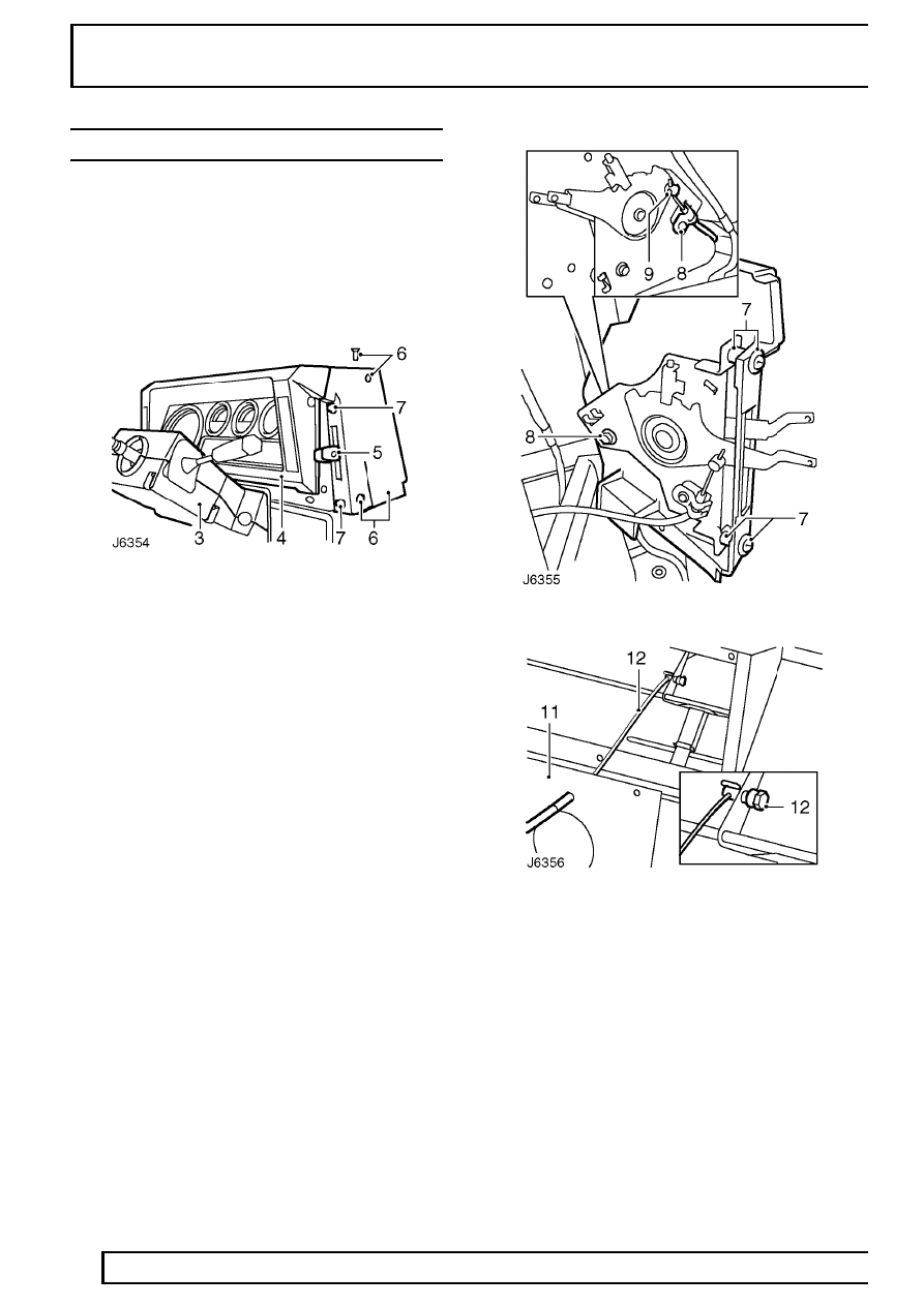
5. Remove retaining screws and pull off air
distribution and temperature control lever knobs.
6. Remove 3 screws and detach side cover,
complete with control lever assembly.
7. Remove 2 screws securing control lever
assembly to side cover and remove cover. Note
plastic screw spacers fitted between cover and
control lever assembly and retain.
8. Remove small bolt and release outer cable
retaining clip.
9. Slacken grub screw and release inner cable from
clevis.
10. Remove lower fascia panel assembly
See
CHASSIS AND BODY, Repair, Lower fascia
panel (heater duct) assembly.
11. Remove 19 screws and lift off heater duct cover.
12. Slacken vent flap trunnion fixing, release air
distribution control cable and remove from
heater duct.
13. Check condition of foam sealant on heater duct
cover and renew if necessary.
HEATING AND VENTILATION
7
REPAIR
Refit
14. Fit new control cable through heater duct cover
and secure to vent flap trunnion. Bend over
cable end to fully secure.
15. Fit heater duct cover.
16. Fit lower fascia panel assembly to fascia
bulkhead
See CHASSIS AND BODY, Repair,
lower fascia panel (heater duct) assembly.
17. Route control cable along fascia bulkhead to
contol lever assembly.
18. With control lever in closed position, secure
cable to clevis.
19. Fit outer cable retaining clip to lever assembly.
20. Fit lever assembly to side cover. Ensure screw
spacers are fitted between cover and lever
assembly.
21. Fit side cover to fascia cowl.
22. Fit control lever knobs.
23. Fit instrument panel
See INSTRUMENTS,
Repair, Instrument panel.
24. Fit steering column nacelle
See STEERING,
Repair, Steering column nacelle.
CONTROL CABLE AND BLOWER MOTOR SWITCH
Service repair no - 80.10.17 - Control cable
Service repair no - 80.10.22 - Blower motor switch
Remove
1. Disconnect battery.
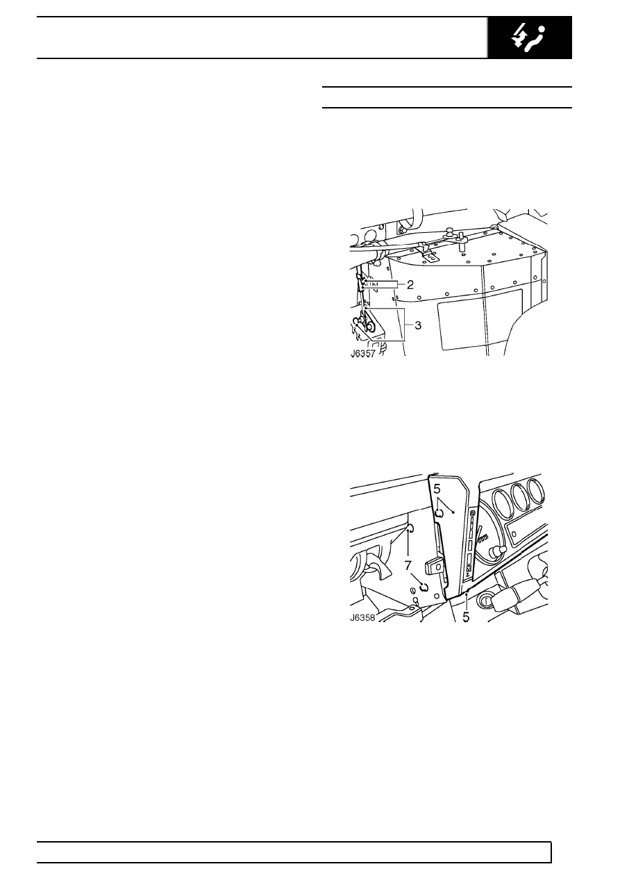
2. From inside engine compartment, release outer
cable retaining clip at heater unit.
3. Slacken trunnion fixing and release inner cable
from heater unit flap lever.
4. Release 2 retaining clips securing control cables
to engine bulkhead and heater hoses.
5. Remove 4 screws securing instrument panel to
fascia cowl.
6. Pull instrument panel away from fascia and
disconnect speedometer cable to ease access to
control cable.
7. Remove 2 screws securing control lever
assembly to side of fascia panel cowl. Note
plastic screw spacers fitted between cowl and
lever assembly and retain.
80
HEATING AND VENTILATION
8
REPAIR
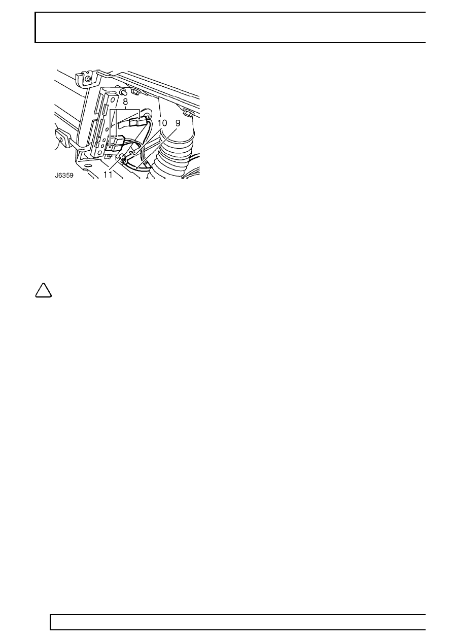
8. Release lever assembly and disconnect 3
blower motor leads, noting their positions.
9. Pull control cable through bulkhead grommet
and out from instrument panel cowl.
10. Release retaining clip securing outer cable to
lever assembly.
11. Release inner cable from lever peg.
NOTE: If the blower motor switch is faulty
the complete lever assembly will have to
be renewed.
Refit
12. Fit new control cable to lever assembly peg.
13. Fit retaining clip to secure outer cable.
14. Reconnect blower motor leads.
15. Route cable to rear of instrument panel cowl,
along bulkhead and out through grommet into
engine compartment.
16. Fit lever assembly to panel cowl. Ensure screw
spacers are fitted between cowl and lever
assembly.
17. Fit instrument panel to fascia cowl.
18. With lever in closed position, fit control cable to
heater unit flap lever trunnion.
19. Secure outer cable with retaining clip.
20. Secure control cables to engine bulkhead and
heater hoses with retaining clips.
21. Reconnect battery.
AIR CONDITIONING
1
DESCRIPTION AND OPERATION
AIR CONDITIONING SYSTEM
Description
Air conditioning is an optional system which provides
fully integrated climate control for the vehicle interior.
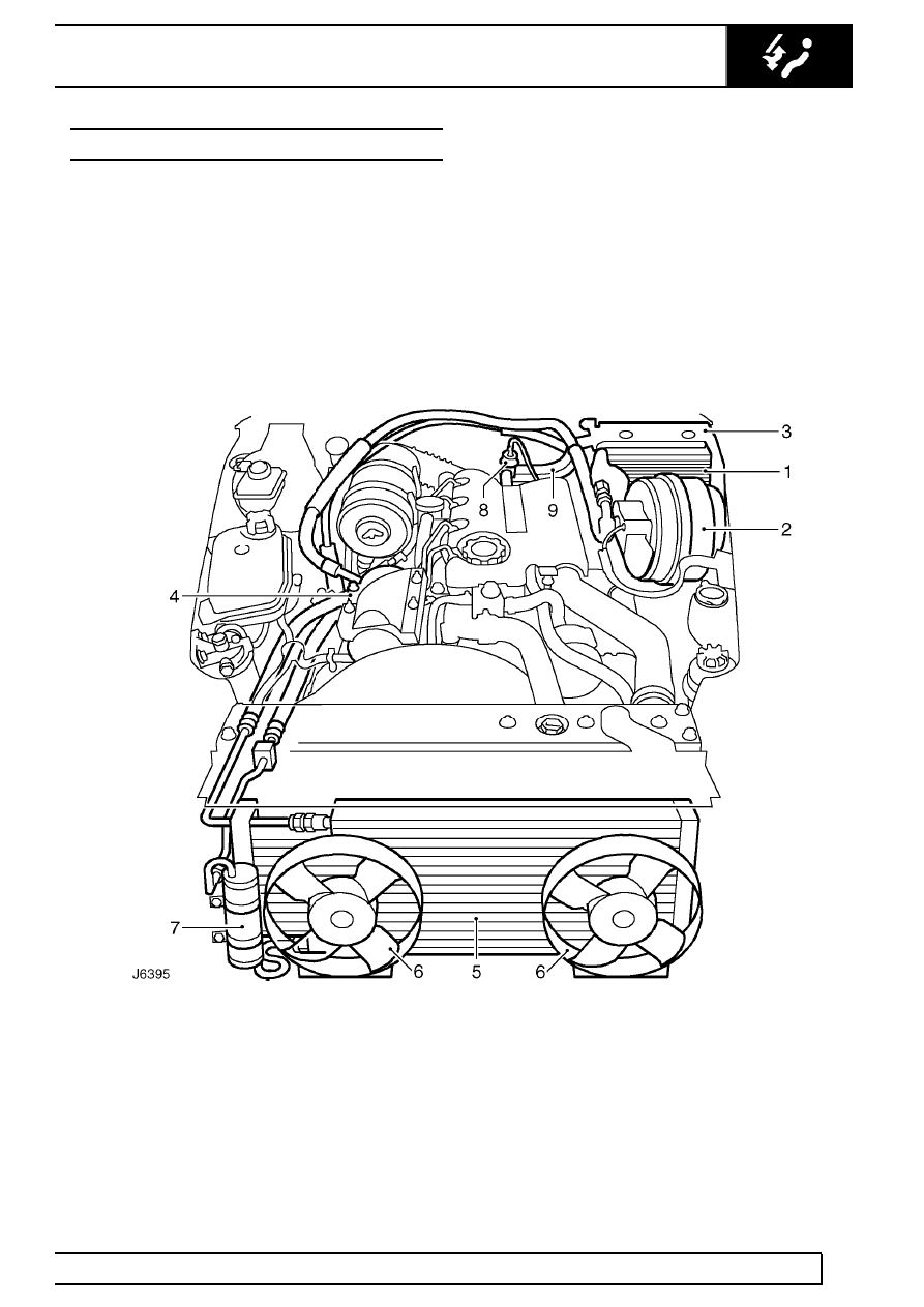
The air conditioning system comprises four major
units as follows:- An evaporator matrix and expansion
valve (1), housed in the heater/ cooler unit (3), an
engine mounted compressor (4), a condenser (5),
mounted in front of the radiator, and a receiver/drier
(7) located to the right of the condenser.
Ancillary components in the system comprise a blower
motor (2), also housed in the heater/cooler unit, and
condenser cooling fan motors (6), mounted on a
support frame. The four major units are interconnectd
by preformed metal and flexible refrigerant pipes as
illustrated below (RH drive installation shown).
Coolant flow to a heater matrix, housed in the heater
cooler unit, is controlled by a water valve (8) from a
combined air conditioning panel on the vehicle fascia.
1. Evaporator matrix and expansion valve
2. Blower motor
3. Heater/cooler unit
4. Compressor
5. Condenser
6. Condenser fan motors
7. Receiver/drier
8. Water valve
9. Heater matrix feed and return hoses
Нет комментариевНе стесняйтесь поделиться с нами вашим ценным мнением.
Текст