Discovery 2. Manual — part 421
ENGINE - TD5
OVERHAUL 12-1-81
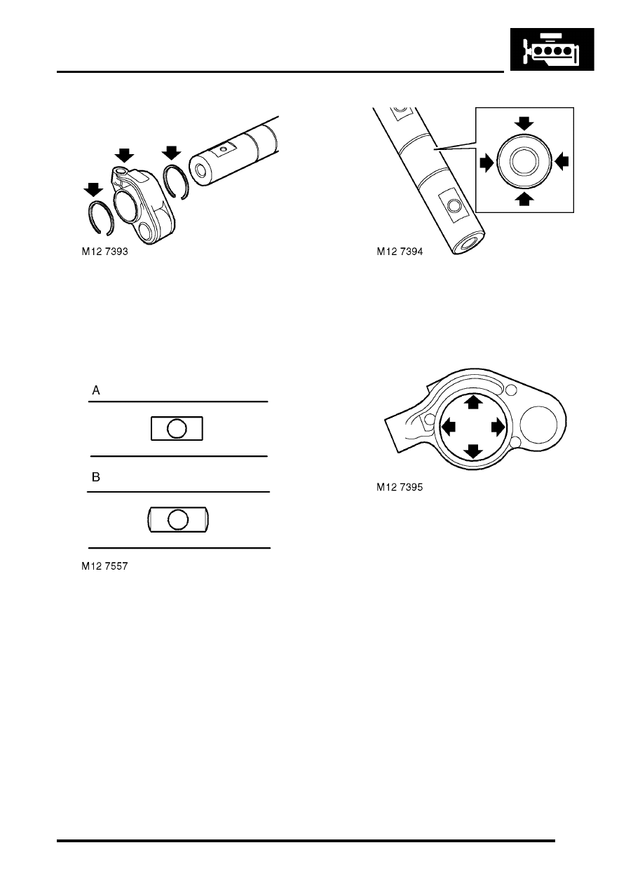
54. Remove and discard spring ring retaining
rocker arm on shaft.
55. Remove rocker arm. Remove and discard 2nd
spring ring.
56. Repeat above procedures for remaining rocker
arms keeping them in their fitted order.
57. Clean rocker arms and shaft, ensure oilways
are clear.
CAUTION: Identify type of rocker shaft
fitted. Engine Serial No. Prefixes 10P to 14P
– Type A rocker shaft; Engine Serial No.
Prefixes 15P to 19P – Type B rocker shaft.
Type B rocker shafts and arms may be fitted
to Engine Serial No. Prefixes 10P to 14P as
an assembly.
58. Check diameter of each rocker arm journal on
shaft, take 2 measurements at 180
°
:
l
Journal diameter = 26.971 to 26.998 mm
(1.061 to 1.063 in)
59. Using a vernier, check internal diameter of
each rocker arm, take 2 measurements at
180
°
:
l
Rocker arm internal diameter = 27.0 to
27.013 mm (1.062 to 1.064 in)
60. Fit new spring ring to groove in rocker shaft.
61. Lubricate rocker shaft journals and rocker arms
with engine oil.
62. Fit rocker arm to shaft ensuring it is in its
original fitted order.
63. Fit new spring ring to retain rocker arm.
64. Repeat above procedures for remaining rocker
arms ensuring they are in their original fitted
order.
65. Fit new rocker adjusting screws and locknuts to
rocker arms; do not tighten screws fully into
arms at this stage.
CAUTION: Ensure screws are correct for
type of rocker arms fitted. Replacement
screws for Engine Serial No. Prefixes 15P to
19P have a centre punch mark adjacent to
the adjusting slot. These screws are not
interchangeable with those fitted to Engine
Serial No. Prefixes 10P to 14P.
ENGINE - TD5
12-1-82 OVERHAUL
Reassembly
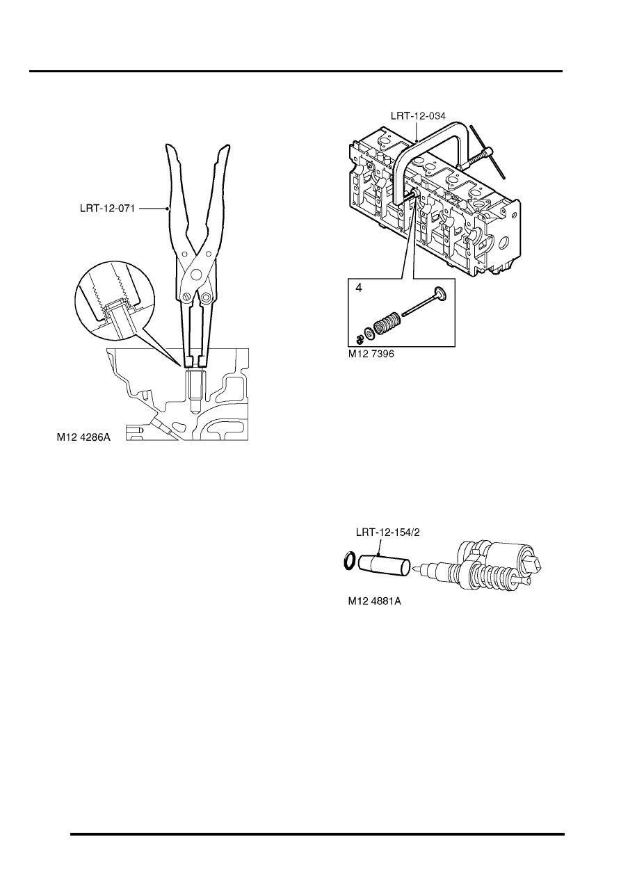
1. Lubricate new valve stem oil seals with engine
oil.
2. Using tool LRT-12-071 fit valve stem oil seals.
3. Lubricate valve guides, valve stems, valve
spring caps and springs with engine oil.
4. Assemble valves, springs and spring caps
ensuring they are in their original fitted order.
5. Compress valve springs using tool LRT-12-
034 , fit collets.
6. Using a wooden dowel and mallet, tap each
spring cap lightly to seat collets.
7. Lubricate new injector 'O' rings with engine oil.
8. Using tool LRT-12-154/2, fit new 'O' ring to
each injector.
ENGINE - TD5
OVERHAUL 12-1-83
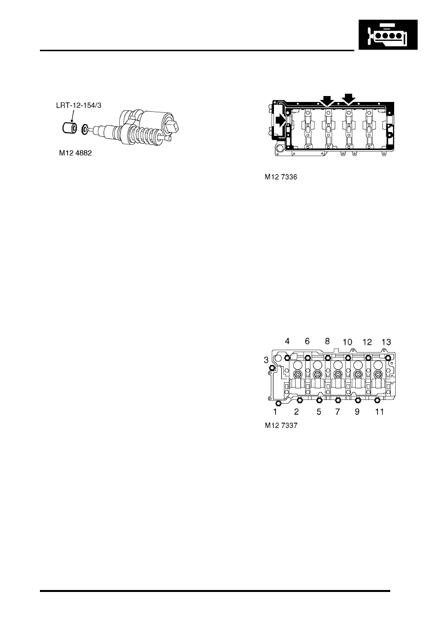
9. Using tool LRT-12-154/3, fit new sealing
washer to each injector.
10. Support each end of cylinder head on blocks of
wood ensuring blocks are clear of valves.
11. Position reaction posts in their original fitted
order.
12. Carefully fit EUI's, ensuring they are in their
original fitted order and that each retainer is
located on its dowel.
CAUTION: If new EUI's are fitted, ensure
replacements are correct. Engine Serial No.
Prefixes 10P to 14P – Push rod bushes are
coloured BLACK or BLUE. Serial No.
Prefixes 15P to 19P – Push rod bushes are
coloured GREEN.
13. Fit new retainer bolts and tighten to 32 Nm (24
lbf.ft).
If new injectors are fitted they must be
programmed for use with the ECM using
TestBook.
14. Lubricate lash adjusters and bores with engine
oil.
15. Fit lash adjusters ensuring they are in their
original fitted order.
16. Lubricate finger followers with engine oil.
17. Fit finger followers ensuring they are in their
original fitted order.
18. Lubricate cams and bearing journals on
camshaft, cylinder head and camshaft carrier
with engine oil.
19. Position camshaft in cylinder head with the
timing pin hole in the vertical position.
20. Apply an even film of sealant, Part No. STC
4600 to camshaft carrier face and spread to an
even film using a roller.
CAUTION: Ensure sealant does not block
oilways (arrowed) or contaminate camshaft
bearings. Assembly and bolt tightening
must be completed within 20 minutes of
applying sealant.
21. Fit camshaft carrier ensuring it is correctly
located on dowels.
22. Fit and lightly tighten new camshaft carrier
bolts.
23. Using sequence shown, progressively tighten
bolts to 25 Nm (18 lbf.ft).
24. Lubricate a new camshaft rear oil seal with
engine oil, fit seal using a suitable mandrel.
25. Position rocker shaft on camshaft carrier
ensuring rocker shaft is located on dowel.
26. Fit new rocker shaft retaining bolts and working
from the centre outwards, tighten rocker shaft
bolts to 32 Nm (24 lbf.ft).
27. Fit injector harness and connect multiplugs.
28. Clean fuel connector block and mating face.
29. Lubricate a new fuel filter 'O' ring with engine
oil.
ENGINE - TD5
12-1-84 OVERHAUL
30. Fit new fuel filter, 'O' ring, and gasket.
CAUTION: Gasket must be fitted dry.
31. If fitted: Fit fuel connector spacer block and
gasket.
32. Fit fuel connector block, fit bolts and tighten to
25 Nm (18 lbf.ft).
33. Clean glow plugs.
34. Fit glow plugs to cylinder head and tighten to
16 Nm (12 lbf.ft).
35. Fit new cylinder head gasket.
ENGINE - Td5, OVERHAUL, Gasket
36. Engine Serial No. Prefixes 15P to
19P:Lubricate new 'O' rings with engine oil and
fit to spill return pipe, fit pipe and tighten
connectors to 20 Nm (15 lbf.ft).
37. Before fitting the camshaft cover, the fuel
injector rockers must be adjusted following the
procedures given in Cylinder head gasket -
Refit.
ENGINE - Td5, OVERHAUL, Gasket
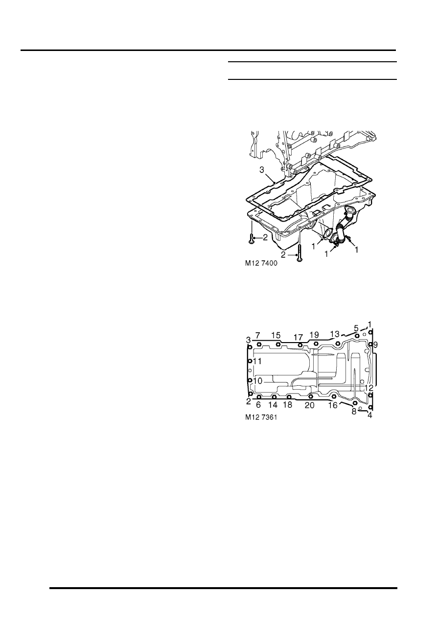
Gasket - engine sump
$% 12.60.38.01
Disassembly
1. Remove 2 bolts securing centrifuge oil drain
pipe to sump, remove and discard gasket.
2. Using sequence shown and noting their fitted
positions, remove 20 bolts securing sump to
cylinder block.
3. Release sump from locating dowels, remove
sump; remove and discard gasket.
Reassembly
1. Clean sump and mating faces, ensure bolt
holes in cylinder block are clean and dry.
2. Using suitable solvent, remove all traces of
sealant from joint faces of timing chain cover
and crankshaft rear oil seal housing.
3. Clean centrifuge oil drain pipe and mating
faces.
Нет комментариевНе стесняйтесь поделиться с нами вашим ценным мнением.
Текст