Discovery 2. Manual — part 419
ENGINE - TD5
OVERHAUL 12-1-73
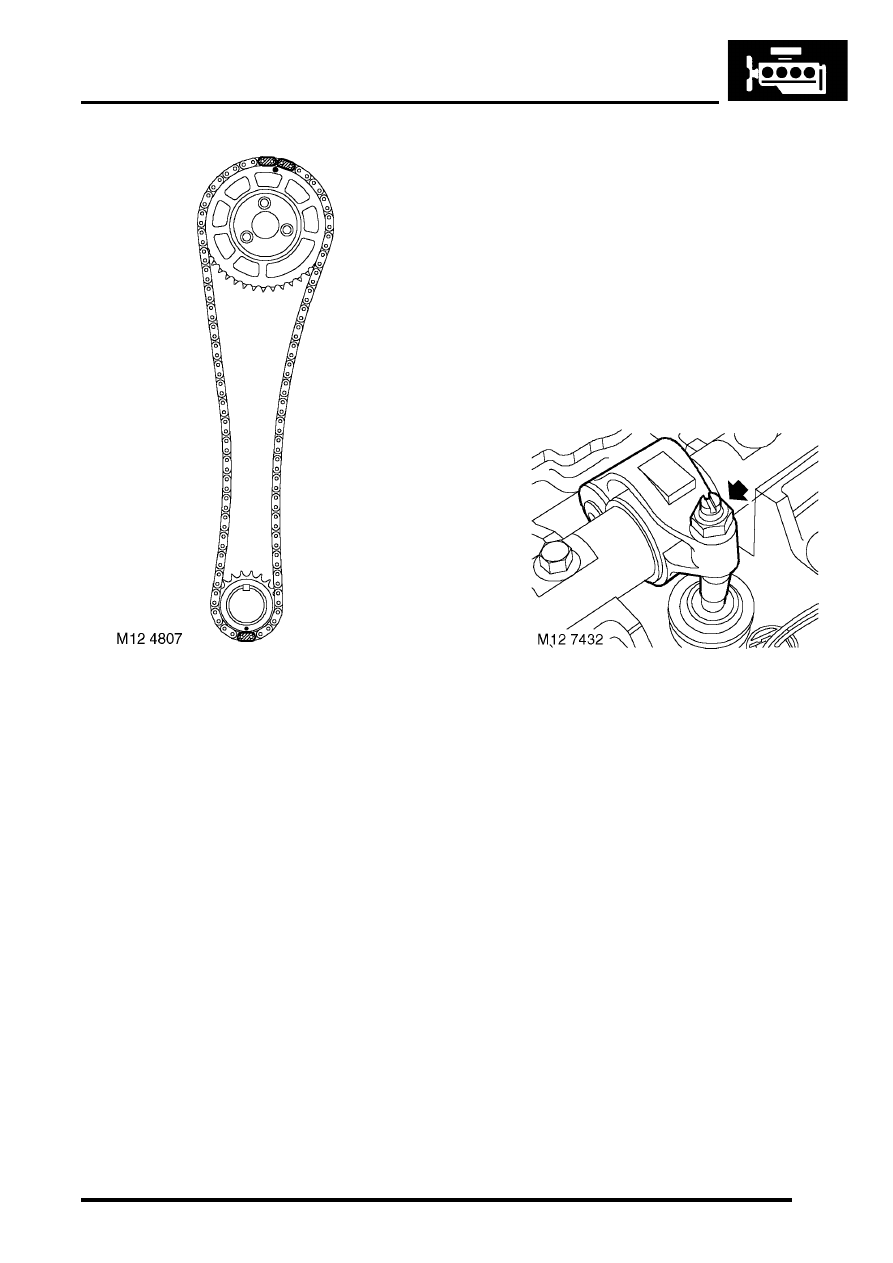
11. Ensure engine is set to TDC firing - No.1
cylinder.
12. Check that mark on camshaft sprocket is
positioned between the 2 coloured links on
timing chain.
13. Position sprocket to camshaft, fit and lightly
tighten 3 new bolts then loosen bolts half a
turn.
14. Clean fixed guide Allen screw and apply
Loctite 242 to screw threads.
15. Fit fixed timing chain guide Allen screw and
tighten to 25 Nm (18 lbf.ft).
16. Clean timing chain tensioner and fit new
sealing washer.
17. Fit timing chain tensioner and tighten to 45 Nm
(33 lbf.ft).
18. Tighten camshaft sprocket bolts to 37 Nm (27
lbf.ft).
19. Remove tool LRT-12-058 from camshaft.
20. Lubricate a new 'O' ring with engine oil and fit to
camshaft sprocket access plug.
21. Fit camshaft sprocket access plug.
22. Clean alternator/vacuum pump oil hose union.
23. Lubricate a new 'O' ring with engine oil and fit to
alternator/vacuum pump oil hose union.
24. Fit and tighten alternator/vacuum pump oil
hose union to 10 Nm (7 lbf.ft).
25. Fit bolt securing alternator strap bracket to
cylinder head and tighten to 25 Nm (18 lbf.ft).
26. Connect multiplugs to ECT sensor and EUI's.
CAUTION: Following cylinder head
overhaul, it will be necessary, before fitting
the camshaft cover to adjust the fuel
injector rockers using the following
procedures:
27. Rotate engine clockwise until No.1 EUI lobe is
at full lift.
28. Tighten No.1 rocker adjusting screw until the
EUI plunger is felt to 'bottom out'.
29. Loosen rocker adjusting screw 1 complete turn
to give EUI plunger the required bump
clearance and tighten rocker adjusting screw
to 16 Nm (12 lbf.ft).
CAUTION: Ensure screw does not turn as
locknut is tightened.
30. Carry out the above procedures for the
remaining 4 rocker arms.
31. After completion of rocker adjustment, slowly
rotate engine clockwise 2 complete turns by
hand to ensure that no EUI's are bottoming out
on their plungers.
32. Clean camshaft cover and mating face.
33. Fit new sealing washers and isolators as
necessary to camshaft cover.
34. Fit new camshaft cover gasket to cover.
CAUTION: Gasket must be fitted dry.
ENGINE - TD5
12-1-74 OVERHAUL
35. Fit camshaft cover to camshaft carrier, fit bolts
and working from the centre outwards tighten
bolts to 10 Nm (7 lbf.ft).
36. Fit inlet manifold gasket.
ENGINE - Td5, OVERHAUL, Gasket
37. Fit exhaust manifold gasket.
ENGINE - Td5, OVERHAUL, Gasket
38. EGR cooler fitted: Position EGR pipe to
cooler, fit new Allen screws and tighten to 10
Nm (7 lbf.ft)
Cylinder head - overhaul
$% 12.29.19.01
Disassembly
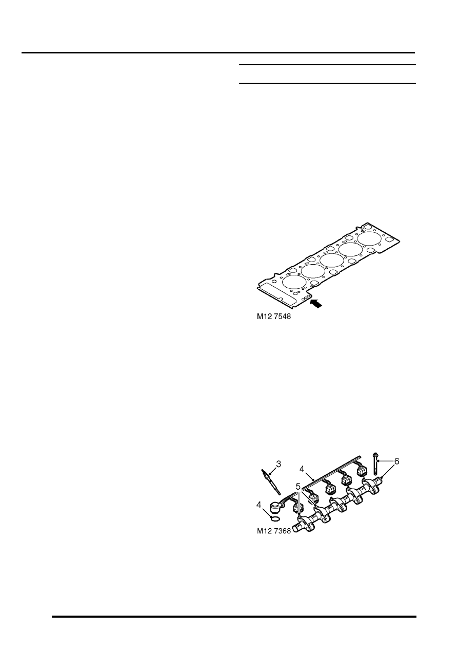
1. Remove cylinder head gasket. Due to the
design of the cylinder head, which
incorporates drillings for the fuel injection
system, it is important that absolute
cleanliness is adhered to when carrying out
any work to the cylinder head.
ENGINE - Td5, OVERHAUL, Gasket
2. Note the gasket thickness indicator and ensure
the same thickness gasket is used on refitment
of cylinder head.
CAUTION: If new pistons, connecting rods
or crankshaft are to be fitted, it will be
necessary to measure piston stand proud in
order to determine thickness of gasket
required – See Pistons, Connecting rods
and Cylinder Bores – Cylinder head gasket
selection.
3. Remove 4 glow plugs.
4. Disconnect multiplugs from EUI's and remove
harness from camshaft carrier. Remove and
discard 'O' ring from harness multiplug.
ENGINE - TD5
OVERHAUL 12-1-75
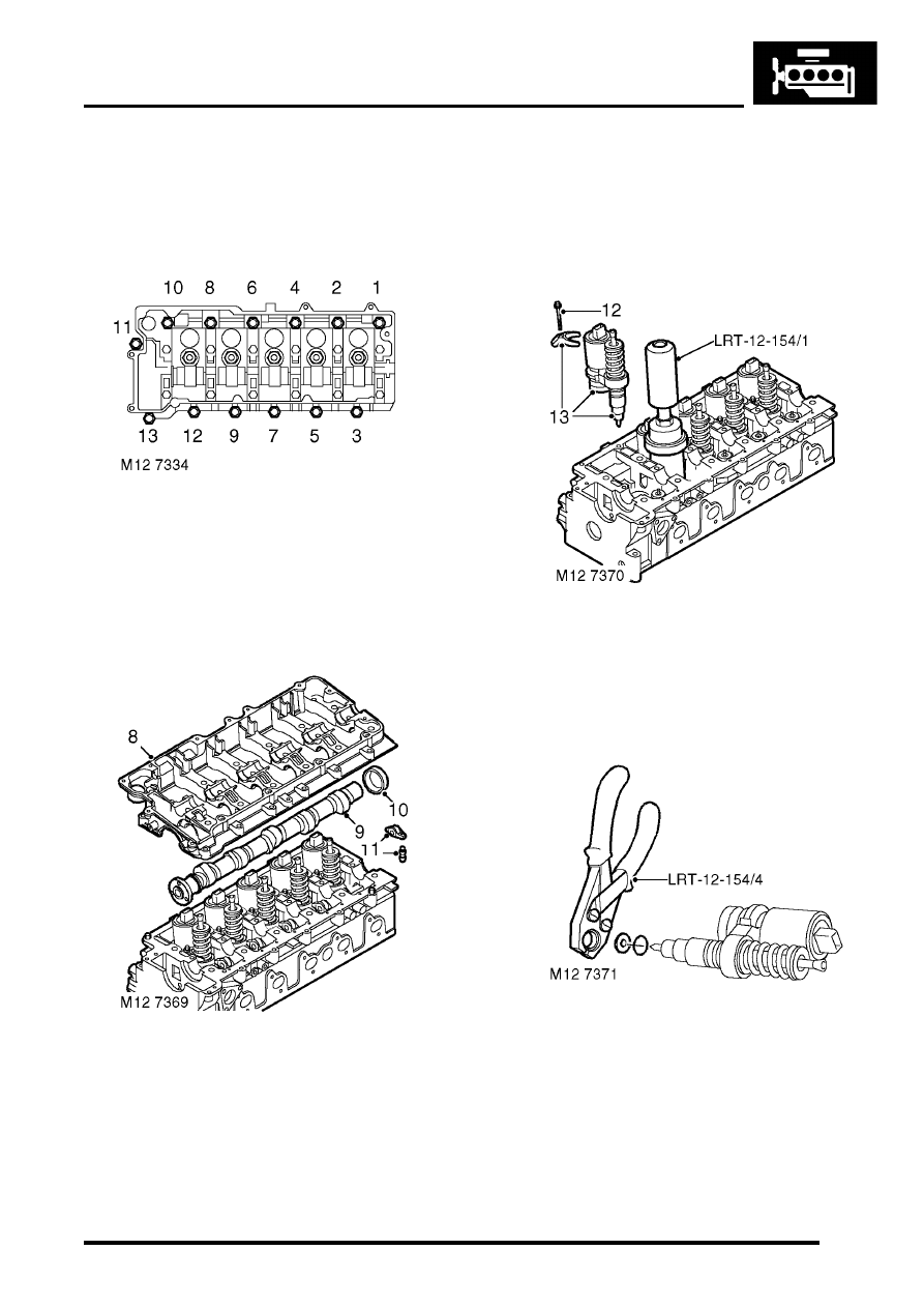
5. Loosen locknuts and fully unscrew rocker
adjusting screws; discard locknuts and screws.
6. Remove and discard 6 bolts securing rocker
shaft, release shaft from locating dowel and
remove shaft.
7. Using sequence shown, progressively loosen
13 bolts securing camshaft carrier to cylinder
head until valve spring pressure is released;
remove bolts. Do not discard bolts at this
stage.
8. Gently tap camshaft carrier upwards to break
sealant bond, release carrier from locating
dowels; remove carrier.
9. Remove camshaft.
10. Remove and discard camshaft rear oil seal.
11. Remove finger followers and lash adjusters.
CAUTION: Store lash adjusters in their fitted
order and store upright. Maintain absolute
cleanliness when handling lash adjusters.
Failure to observe these precautions can
result in engine failure.
12. Remove and discard 5 bolts securing EUI
retainers.
13. Using tool LRT-12-154/1 remove EUI units
from cylinder head and collect retainers;
remove reaction posts. Keep components in
their fitted order.
14. Using tool LRT-12-154/4, remove and discard
sealing washer and 'O' ring from each injector
unit.
15. Support cylinder head clear of valves, use a
hollow drift and tap each spring cap to free
collets.
ENGINE - TD5
12-1-76 OVERHAUL
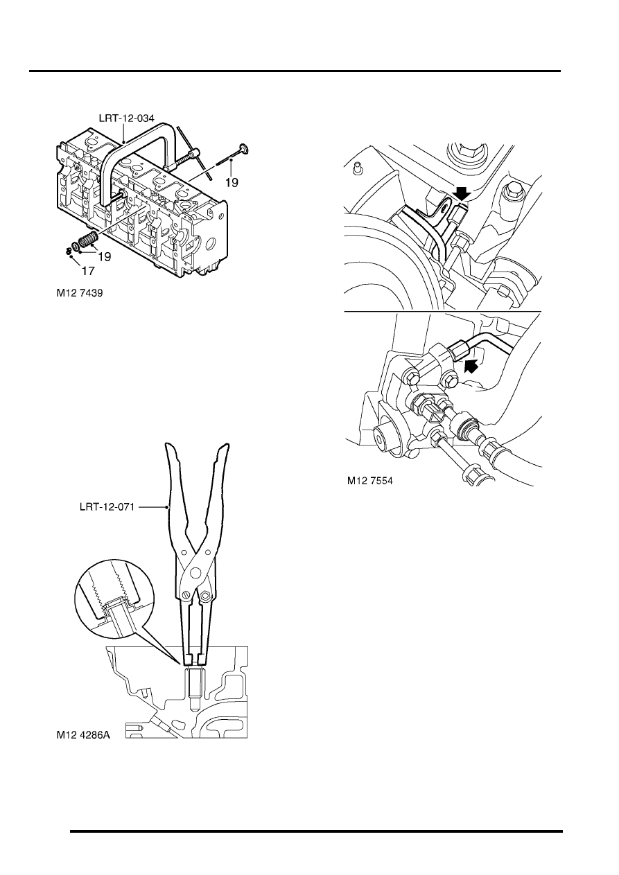
16. Using tool LRT-12-034 compress valve
spring.
17. Remove 2 collets from valve stem using a stick
magnet.
18. Remove tool LRT-12-034 .
19. Remove valve spring cap, valve spring and
valve. Keep components in their fitted
order.
20. Using tool LRT-12-071, remove and discard
valve stem oil seal.
21. Repeat above operations to remove remaining
valves. Keep components in their fitted
order.
22. Engine Serial No. Prefixes 15P to
19P:Disconnect spill return pipe from cylinder
head and fuel connector block, remove and
discard 'O' rings.
Нет комментариевНе стесняйтесь поделиться с нами вашим ценным мнением.
Текст