Discovery 2. Manual — part 39
ENGINE - V8
REPAIRS 12-2-29
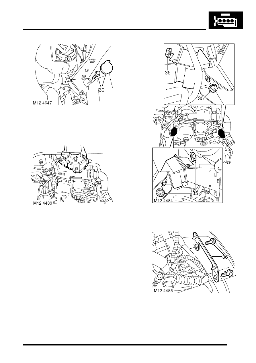
30. Models with automatic gearbox: Remove
access plug and remove 4 bolts securing
torque converter to drive plate.
31. Rotate engine to access bolts.
32. Remove 12 bolts securing engine to gearbox.
DO NOT remove the top 2 bolts at this
stage.
33. Collect support brackets from bell housing
bolts.
34. Attach suitable lifting equipment to engine.
35. Remove 4 nuts securing engine mountings,
raise engine and remove engine mountings.
36. Lower engine, remove top bolts securing
engine to gearbox and collect bracket.
37. Support gearbox on a jack.
38. Release engine from gearbox dowels.
39. With assistance remove engine from engine
bay.
ENGINE - V8
12-2-30 REPAIRS
Refit
1. Clean mating faces of engine and gearbox,
dowel and dowel holes.
2. Lubricate splines and bearing surface on first
motion shaft with grease.
3. With assistance position engine in engine bay,
align to gearbox and locate on dowels.
4. Position support brackets, fit bell housing bolts
and tighten to 50 Nm (37 lbf.ft).
5. Position engine mountings, fit nuts and tighten
to 85 Nm (63 lbf.ft).
6. Lower lifting equipment and remove from
engine.
7. Models with automatic gearbox: Align torque
converter to drive plate, fit bolts and tighten to
50 Nm (37 lbf.ft). Fit access plug.
8. Fit exhaust front pipe.
SYSTEMS - V8, REPAIRS, Front pipe.
9. Position oil cooling pipe saddle clamps and
tighten bolts.
10. Position engine harness into foot well.
11. Connect 5 multiplugs to ECM.
12. Fit toe board and secure with trim fixings.
13. Connect engine harness earth to body and
secure with nut.
14. Connect engine harness to main harness
multiplug.
15. Connect multiplug to EVAP purge valve.
16. Connect engine harness multiplugs to fuse
box.
17. Connect starter lead to fuse box and secure
with nut.
18. Connect engine harness positive lead to
battery and tighten nut.
19. Fit fuse box cover.
20. Position engine earth lead and secure with
bolt.
21. Position coolant rail and secure with bolt.
22. Connect harness clips to coolant rail.
23. Connect hose to coolant rail and coolant pump
and secure with clips.
24. Connect PAS pump high and low pressure
pipes and secure with clips.
25. Position oil cooling pipe saddle clamp to PAS
pump housing and secure with bolt.
26. Clean A/C compressor and housing mating
faces, dowels and dowel holes.
27. Position A/C compressor, fit bolts and tighten
to 22 Nm (16 lbf.ft).
28. Connect multiplug to A/C compressor.
29. Clean ACE pump and housing mating faces,
dowels and dowel holes.
30. Position ACE pump, fit bolts and tighten to 22
Nm (16 lbf.ft).
31. Clean all pulley 'V's, fit auxiliary drive belt,
using a 15mm spanner, release belt tensioner
secure belt and re-tension drive belt .
32. Ensure auxiliary drive belt is correctly located
on all pulleys.
33. Fit radiator.
34. Fit top hose and secure with clips.
35. Connect fuel pipe to fuel rail.
36. Position ignition coils and connect ht leads.
37. Fit upper inlet manifold.
SYSTEMS - V8, REPAIRS, Gasket - inlet
manifold - upper - Without Secondary Air
Injection.
38. Fit new oil filter and refill engine with oil.
ENGINE - V8, REPAIRS, Filter - oil.
39. Top up gearbox oil.
ENGINE - V8
REPAIRS 12-2-31
Flywheel
$% 12.53.07
Remove
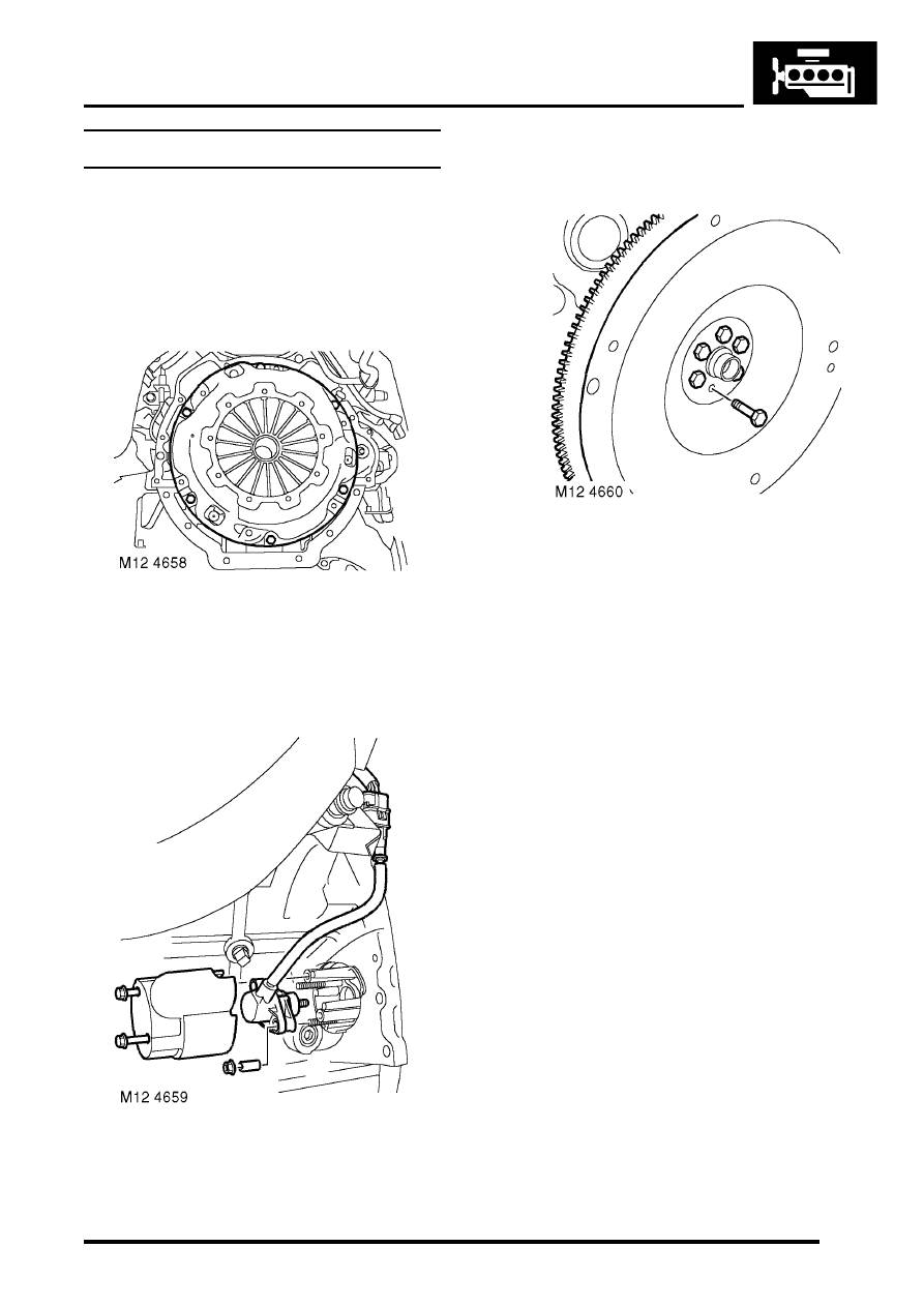
2. Restrain flywheel.
3. Working in sequence, progressively slacken 6
bolts securing clutch cover to flywheel.
Remove bolts.
4. Remove clutch cover.
5. Remove clutch plate.
6. Release crankshaft sensor multiplug from
bracket.
7. Remove 2 bolts securing crankshaft sensor
cover.
8. Remove crankshaft sensor cover.
9. Remove 2 nuts securing crankshaft sensor.
10. Remove crankshaft sensor.
11. Remove 6 bolts securing flywheel.
12. Remove flywheel.
On early engines, balance weights are on
engine side of flywheel; replacement flywheels
will have balance weights on clutch side of
flywheel.
Refit
1. Clean mating faces of flywheel and crankshaft,
dowel and dowel hole. Ensure bolt holes in
crankshaft are clean and dry.
2. Fit flywheel to crankshaft and tighten bolts to
78 Nm (58 lbf.ft).
3. Clean crankshaft sensor and mating face.
4. Fit crankshaft sensor and tighten nuts to 6 Nm
(4.4 lbf.ft).
5. Fit crankshaft sensor cover and tighten bolts to
6 Nm (5 lbf.ft).
6. Fit crankshaft sensor multiplug to bracket.
7. Clean clutch cover, drive plate and spigot bush
in end of crankshaft. Renew worn components
as necessary.
8. If refitting existing drive plate, apply 'Molycote
FB 180' to splines.
ENGINE - V8
12-2-32 REPAIRS
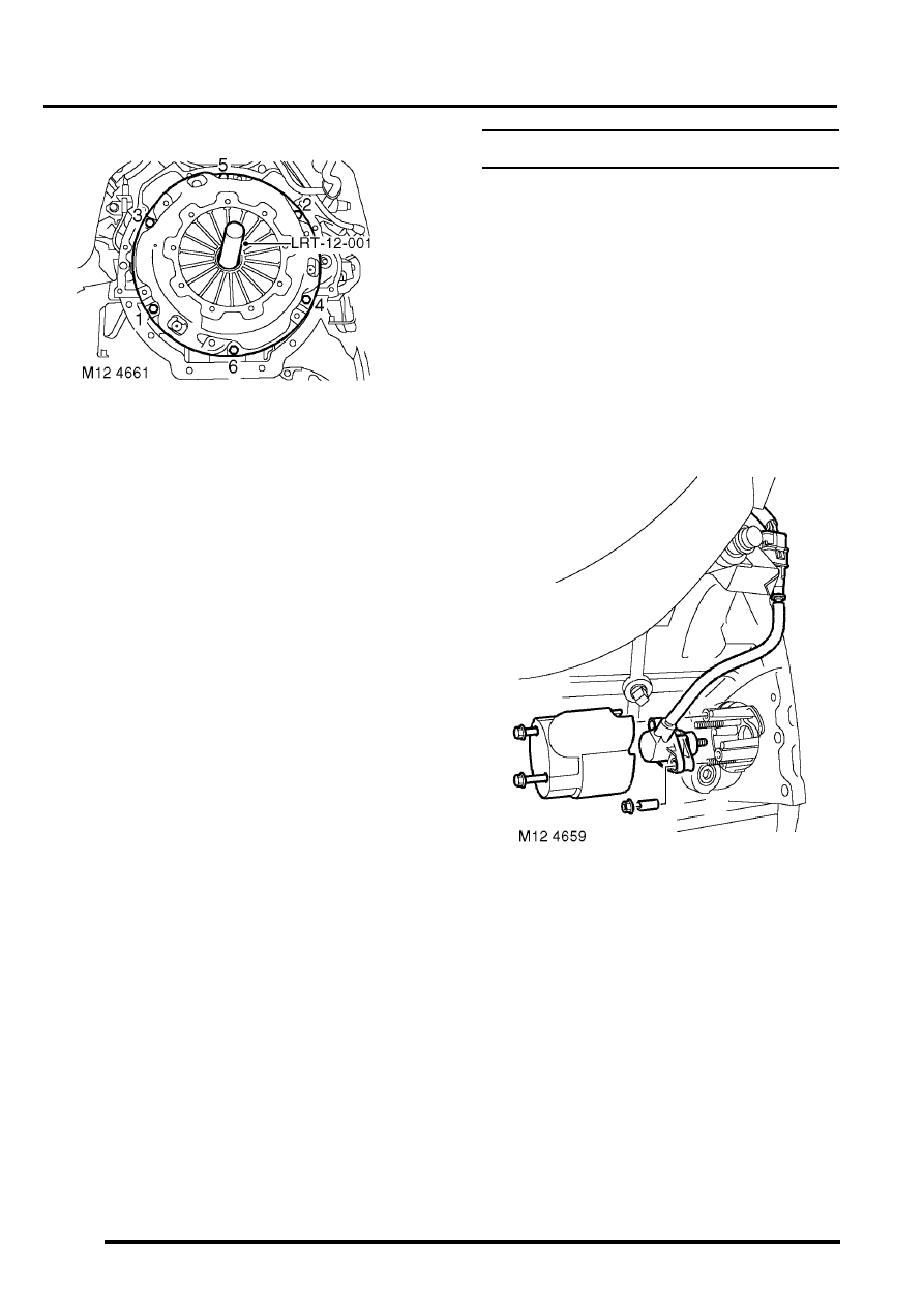
9. Fit alignment tool LRT-12-001 to spigot
bearing in crankshaft.
10. Fit drive plate onto tool LRT-12-001 ensure
side marked 'flywheel side' is towards flywheel.
11. Fit clutch cover and locate on dowels.
12. Fit clutch cover bolts and tighten in diagonal
sequence to 40 Nm (30 lbf.ft).
13. Fit gearbox assembly.
Plate - drive - automatic
$% 12.53.13
Remove
Note: Later engines are fitted with a modified
starter ring gear which incorporates the reluctor
plate, spacer and hub. The modified ring gear
may be fitted as a replacement to early
engines.
1. Remove automatic gearbox.
- 24, REPAIRS, Gearbox - convertor and
transfer gearbox - V8.
2. Remove 2 bolts securing CKP sensor cover.
3. Remove CKP sensor cover.
4. Remove 2 nuts securing CKP sensor.
5. Remove CKP sensor.
Нет комментариевНе стесняйтесь поделиться с нами вашим ценным мнением.
Текст