Defender (1993+). Manual — part 22
ENGINE
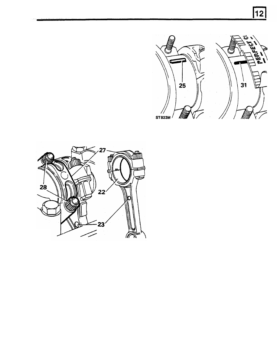
Examine connecting rods
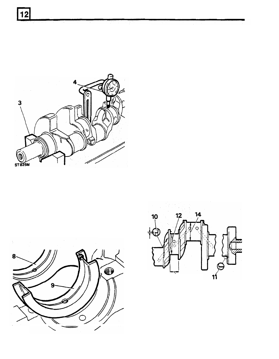
20. Check alignment of connecting rod.
21. Check connecting rod small end, piston pin
must be a press fit.
Check crankshaft bearings
22. Locate bearing upper shell into the connecting
rod.
23.
Locate connecting rod and bearing
onto its
NOTE: Domed shape boss on connecting
rod must face towards front of engine
on
right hand bank of cylinders and towards
rear on left hand bank.
24.
When both connecting rods are fitted, bosses
30. Remove connecting rod cap and shell.
will
face inwards towards each other.
31.
Using scale printed on Plastigauge packet,
measure flattened Plastigauge at its widest
point.
32.
The graduation most closely corresponding
to
width
of
Plastigauge indicates bearing
clearance.
33. Correct bearing clearance with new or
overhauled components is 0.015
to
0.055
mm.
34. If a bearing has been in service,
fit
a new
bearing
if
clearance exceeds
0.08
mm.
35.
If a new bearing is being fitted, use selective
assembly
to
obtain correct clearance.
36. Wipe
off Plastigauge with an oily rag. DO
NOT scrape
it
off.
NOTE: It is important that connecting rods,
caps and bearing shells be retained
in
sets, and in correct sequence.
ST822M
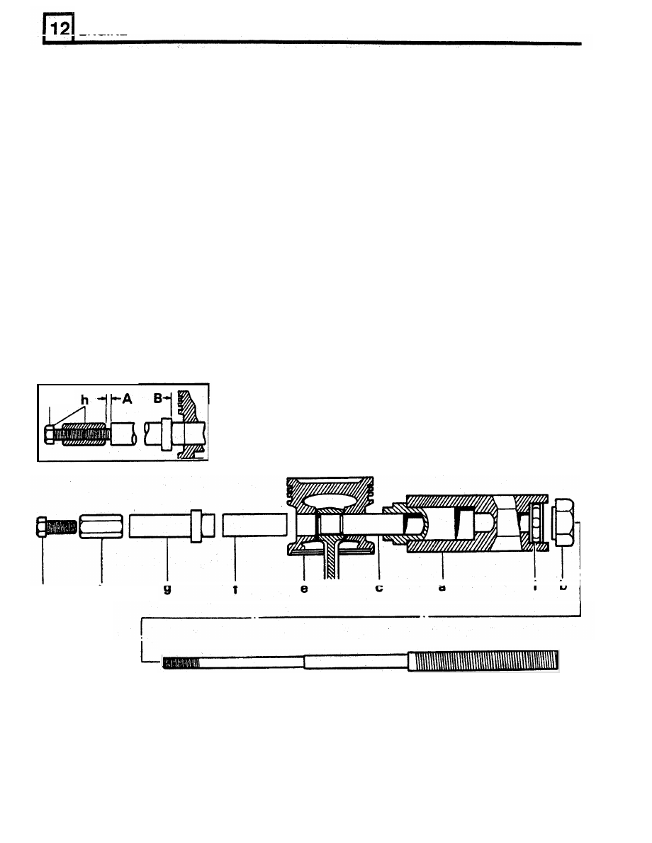
Assembling pistons to connecting rods
25.
Place a piece of Plastigauge (P61) across
centre of lower half of crankshaft journal.
37. Using tool LRT-12-013 refit each piston
to
its
26.
Locate bearing lower shell into connecting rod
connecting rod as follows:
cap.
27. Locate cap and shell onto connecting rod.
a.
Clamp hexagon body of LRT-12-013
in a vice, with adaptor LRT-12-014
NOTE: Note that rib
on
edge
of cap must
positioned as instruction 7d.
be o n same side as domed shape
boss on
Remove large nut of LRT-12-013 and
connecting rod.
push the centre screw approximately
50 mm into body until shoulder is
28. Secure connecting rod cap. Tighten
to
50 Nm.
exposed.
29.
Do
not rotate crankshaft while Plastigauge is
C.
Slide parallel guide sleeve, grooved
end last, onto centre screw and up
to
shoulder.
b.
in use.
crankshaft journal.
ENGINE
k
d.
Lubricate piston pin and bores
of
j.
Set a torque spanner
to 16
Nm. This
connecting rod and piston with
represents minimum load for an
graphited oil (Molykote 2). Also
acceptable interference
fit
of
piston
lubricate ball race and centre screw
pin in connecting rod.
of
LRT-12-013.
k.
Using torque spanner and socket
on
Fit connecting rod and piston together
large nut, and holding lock screw, pull
onto tool, with markings aligned
if
piston
pin
in
until
flange
of
fitting original pair, with connecting
remover/replacer bush is 4mm
'B'
rod around sleeve up
to groove.
from face
of piston. This flange must
f.
Fit piston pin into piston bore, up to
not be allowed
to
contact piston.
connecting rod.
g.
Fit remover/replacer bush LRT-12-015
CAUTION: If torque spanner has
with its flanged end towards piston
not reached at least
16
Nm.
pin.
throughout pull, fit of piston pin to
h.
Screw stop nut onto centre screw and
connecting rod
is not acceptable
adjust nut
to
obtain an
0.8
mm end
and
necessitates
fitting
new
float
'A'
on whole assembly, and lock
components. The large nut and
nut securely with screw.
centre screw
of tool must be kept
body and screw large nut up to thrust
race.
e.
I.
Slide assembly back into hexagon
well oiled.
38.
Remove tool and check that piston moves
freely on piston pin and that no damage has
occurred during pressing.
k
h
ST778M

REMOVE AND OVERHAUL CRANKSHAFT
1.
Remove main bearing caps and lower bearing
shells.
Retain
in pairs and mark
with
number
of journal
until it
is decided
if
bearing shells
2.
Lift
out crankshaft and rear oil seal.
ST824M
are to be refitted.
ENGINE
Inspect and overhaul crankshaft
9.
The centre main bearing shell, which controls
crankshaft thrust, has thrust faces increased
3.
To check for straightness, place crankshaft on
in
thickness when more than 0.25 mm
vee-blocks at numbers one and five main
undersize, as shown in following chart.
bearing journals.
10. When a crankshaft is to be reground, thrust
4.
Using a dial indicator, check run-out at centre
faces on either side of centre main journal
main bearing journal.
must be
machined
in accordance with
dimensions in charts
that follow.
Main bearing journal size Thrust face width
Standard
Standard
0.25 mm undersize
Standard
0.50
mm undersize
0.25
mm oversize
11.
For example: If
fitting a
0.50
mm undersize
bearing, 0.125 mm must be machined
off
each thrust face
of centre journal, maintaining
correct radius.
Crankshaft dimensions
12. Radius for all journals except rear main
bearing
is
1.90
to 2.28 mm.
13. Radius for rear main bearing journal is
3.04
mm.
5. Total run-out at each journal should not
14. Main bearing journal diameter, see following
chart.
exceed
0.08
mm.
6.
If crankshaft is bent it is not suitable for
15. Thrust face width, and connecting rod journal
regrinding and should
be renewed.
diameter,
see
following chart.
7.
Check each crankshaft journal for ovality. If
ovality exceeds 0.040 mm around crankshaft
journal, regrind or
fit
a
new crankshaft.
8.
Crankshaft main and connecting rod bearings
are available in following undersizes:
0.25mm
0.50mm
ST826M
RR1793E
13
Нет комментариевНе стесняйтесь поделиться с нами вашим ценным мнением.
Текст