Defender (1993+). Manual — part 20
RR751M
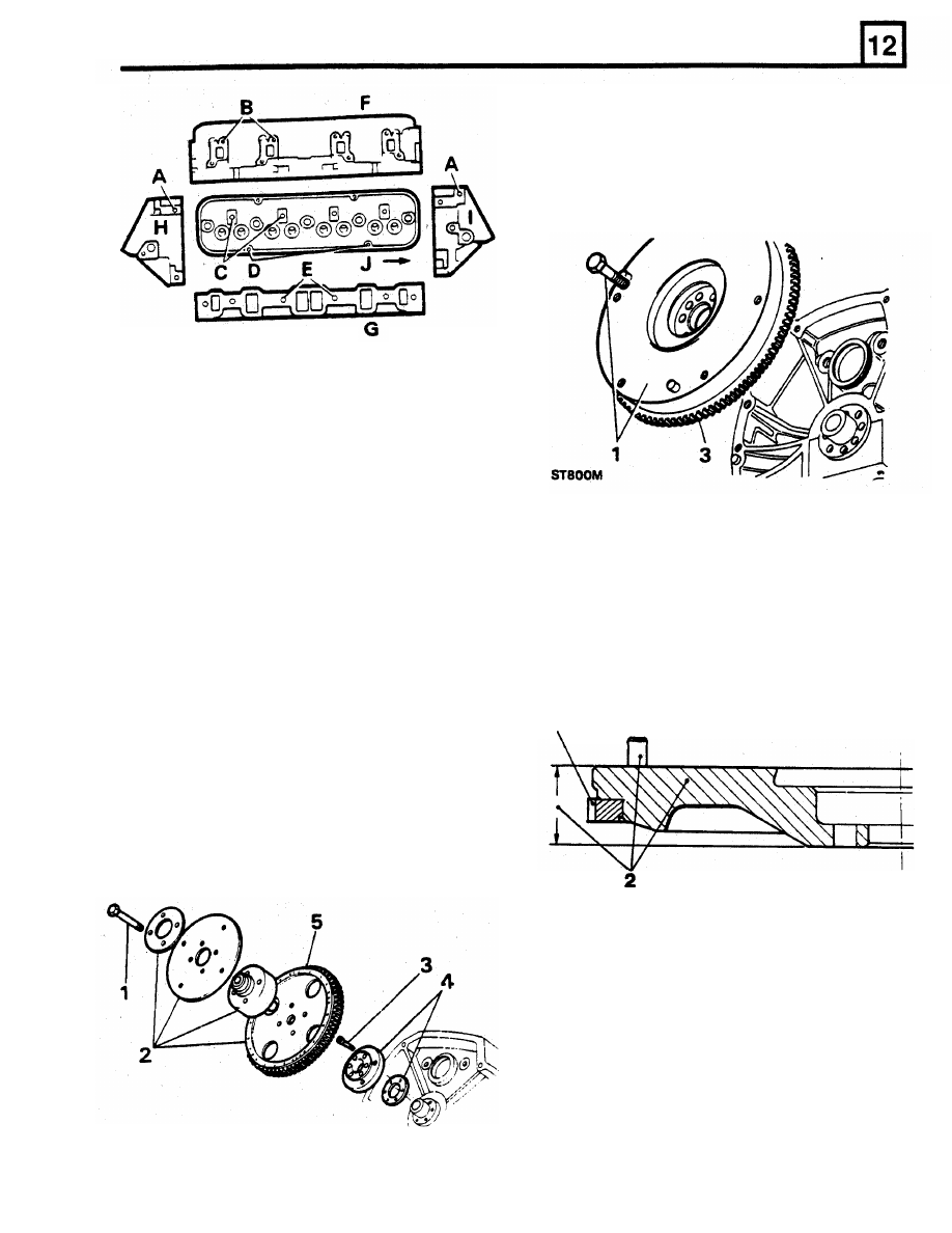
REMOVE AND OVERHAUL FLYWHEEL
1.
Remove retaining bolts and withdraw flywheel
from crankshaft.
NOTE: Right-hand cylinder head illustrated.
F
Exhaust manifold face
G
Intake manifold face
H
Front face
I
Rear face
J
Front of engine
REMOVE FLEXIBLE DRIVE PLATE AND RING
GEAR ASSEMBLY
2. Examine flywheel clutch face for cracks,
scores and overheating. The flywheel can be
NOTE:
Scribe
each
component
with
an
refaced provided m i n i m u m thickness does
identification line to enable re-assembly
in
not go below 39.93 mm
(1.572
in). Remove
original
position.
3. Examine ring gear for worn, chipped and
three dowels before machining.
1.
Remove four retaining bolts.
broken teeth. Renew as follows:
2.
Withdraw clamp ring, flexible drive plate, hub
aligner and ring gear assembly.
3. Remove six socket head bolts securing
crankshaft adaptor plate and shim to
crankshaft flange.
4.
Withdraw crankshaft adaptor plate and shim.
5.
Inspect ring gear assembly for distortion,
cracks, chipped or badly
worn teeth.
If
ring
gear
is in poor condition
fit
a new assembly.
4.
Drill a
10
mm diameter hole axially between
roots of any tooth and inner diameter
of
starter ring sufficiently deep to weaken ring.
DO
NOT allow drill to enter flywheel.
RR1806E
ENGINE
3
ST803M
ENGINE
5.
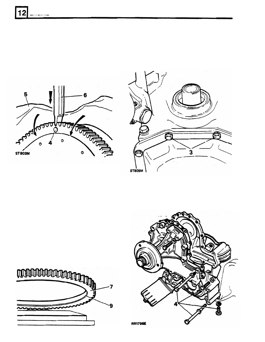
Secure flywheel in a vice using
soft
jaws and
place a cloth over flywheel
to
protect operator
REMOVE TIMING GEAR
COVER
AND WATER
from flying fragments.
PUMP
WARNING: Take adequate precautions
1.
Place an oil drip-tray beneath timing cover,
against flying fragments when splitting
remove oil filter element.
ring gear.
2. Remove crankshaft pulley bolt and special
washer, withdraw pulley.
6.
Place a chisel as shown, strike it sharply
to
split starter ring gear.
7. Heat new ring gear uniformly to between
170
°
C and 175°C,
DO
NOT EXCEED higher
temperature.
8.
Place flywheel, clutch side down, on flat
3. Remove
two
bolts securing sump
to
bottom of
surface.
timing cover.
9.
Locate heated starter ring gear
in position on
4.
Remove timing cover bolts and withdraw
flywheel, with chamfered inner diameter
cover complete with
oil pump.
towards flywheel flange. If starter ring gear is
chamfered both sides, it can
be
fitted
either
way round.
10. Press starter ring gear
firmly against flange
until ring contracts sufficiently to grip flywheel.
11.
Allow flywheel to
cool
gradually.
DO
NOT
HASTEN cooling
in any way, distortion may
occur.
12.
Fit new clutch assembly location dowels to
flywheel.
ST804M
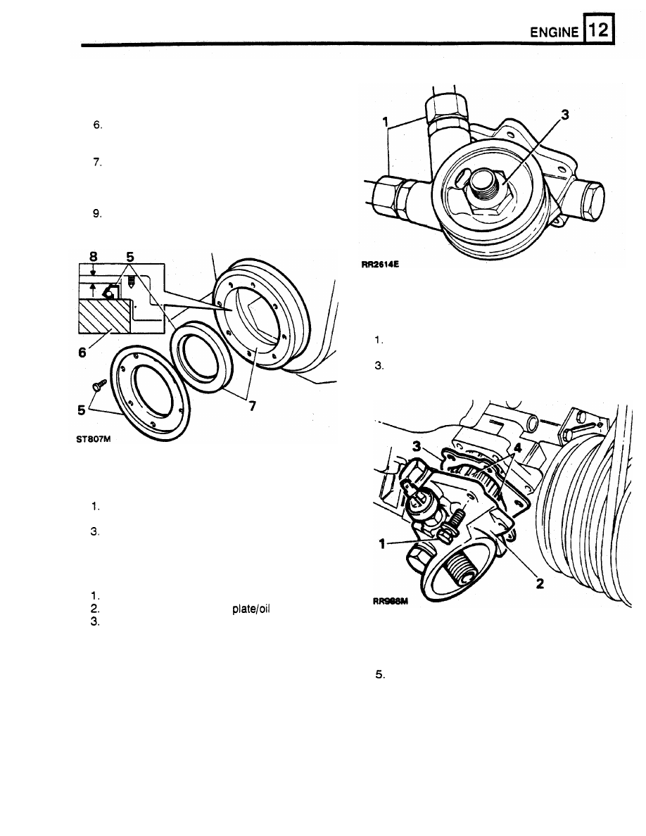
Fit new timing cover oil seal
5.
Remove seven drive screws and withdraw
mud shield and oil seal.
Position gear cover with front face uppermost
and underside supported across oil seal
housing bore on a suitable wooden block.
Enter
oil
seal, lip side leading, into housing
bore.
8.
Press in oil seal until plain face
is
approximately
1,5
mm below gear cover face.
Fit mud shield and securing screws.
REMOVE AND OVERHAUL OIL PUMP
Remove bolts from oil pump cover.
2. Withdraw oil pump cover.
Lift
off cover and remove gasket.
4.
Withdraw oil pump gears.
DISTRIBUTOR REMOVE
Release single nut securing distributor clamp.
2. Remove clamp, withdraw distributor.
If necessary overhaul distributor.
REMOVE ENGINE
OIL
COOLER ADAPTOR
PLATE
Remove both oil cooler pipes.
Mark position
of
adaptor
pump cover.
Remove centre fixing and withdraw adaptor
plate.
Dismantle pump
Refit
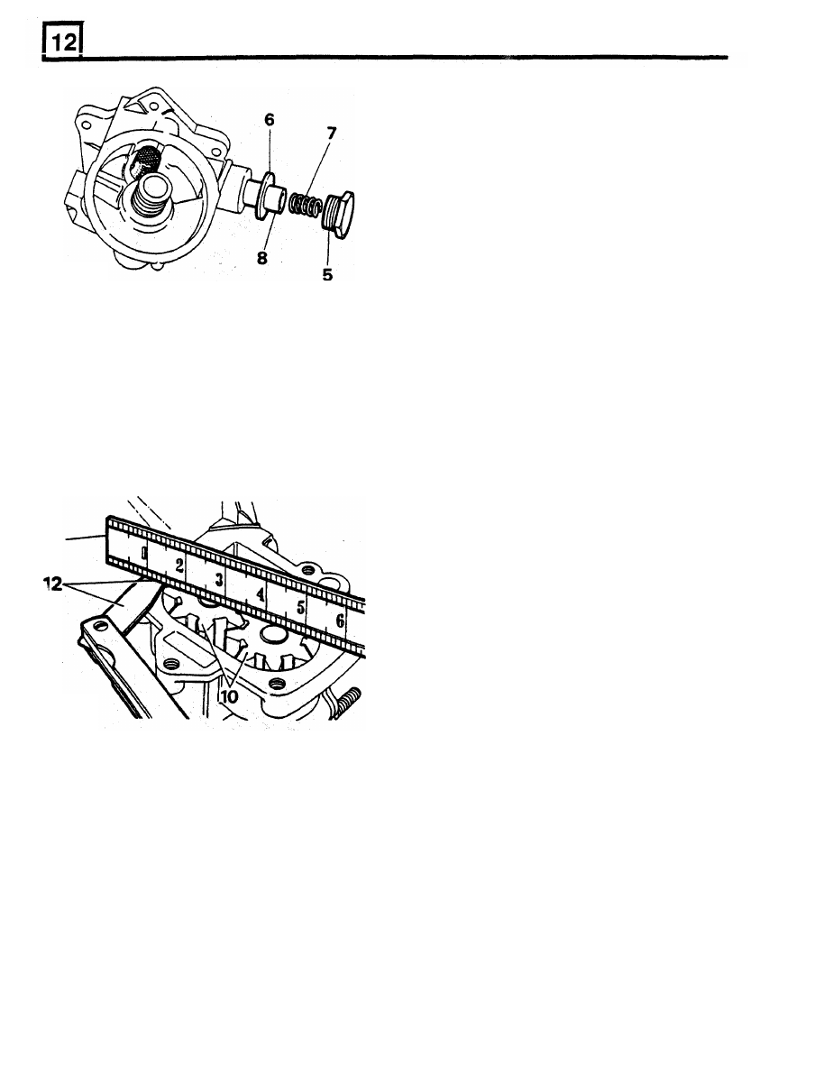
Unscrew plug from pressure relief valve.
4.
Reverse the removal procedure, lining
up
the
6.
Remove sealing washer from plug.
location marks to ensure pipe runs are
7.
Withdraw spnng from relief valve.
correct. Ensure the pipes and centre fixing are
tightened to the specified torque.
8.
Withdraw pressure relief valve.
ENGINE
ST809M
11
Assemble pump
17. Insert relief valve spring.
18.
Locate sealing washer on relief valve plug.
19.
Fit relief valve plug, tighten
to
40
-
47 Nm.
20. Fully pack oil pump gear housing with
Petroleum Jelly.
No other grease is suitable.
21. Fit oil pump gears ensuring that Petroleum
Jelly
is
forced into every cavity between teeth
of gears.
IMPORTANT: Unless pump is fully packed
with Petroleum Jelly
it
may not prime itself
when engine is started.
22. Place new gasket on oil pump cover.
23. Locate oil pump cover
in position.
24. Fit special fixing bolts and tighten to 13 Nm.
Examine pump
9.
Check
oil pump gears for wear/scoring.
10. Fit oil pump gears and shaft into front cover.
11. Place a straight edge across gears.
12. Check clearance between straight edge and
front cover.
lf
less than
0.05
mm, check front
cover gear recess for wear.
13.
Check
oil
pressure
relief
valve
for
wear/scoring.
14. Check sides of relief valve
spring for wear or
signs of collapse.
15. Clean wire screen filter for relief valve.
16.
Check relief valve is an easy slide
fit
with no
perceptible side movement in its bore.
ST810M
Нет комментариевНе стесняйтесь поделиться с нами вашим ценным мнением.
Текст