Defender (1993+). Manual — part 23
ST828M
ENGINE
Crankshaft dimensions-millimetre
Cranks
haft
Diameter
'12'
Width '13'
Diameter
'1 4'
Grade
Standard
58.400-58.412
26.975-27.026
50.800-50.812
0.254
U/S
58.146-58.158
26.975-27.026
50.546-50.558
0.508 U/S
57.892-57.904
27.229-27.280
50.292-50.304
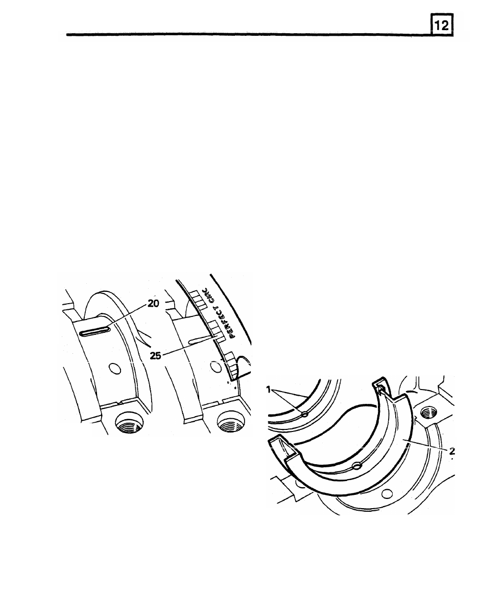
Check main bearing clearance
26. Graduation most closely corresponding
to
width
of
Plastigauge indicates
bearing
16. Remove oil seals from cylinder block and rear
clearance.
main bearing cap.
27. Correct bearing clearance with new
or
17. Locate upper main bearing shells (with oil
overhauled components is 0.023 to 0.065
mm.
hole and oil grooves) into cylinder block.
28.
If
correct clearance is not obtained initially,
18. Locate flanged upper centre main bearing
select a suitable bearing to give required
shell.
clearance.
19. Place crankshaft in position on bearings.
29. Wipe
off Plastigauge with an oily rag.
Do
NOT
20. Place a piece
of Plastigauge across centre
of
crankshaft main bearing journals.
21. Locate lower shells into main bearing caps.
scrape
it
off.
30. Maintain bearing shells and caps in sets,
in
the correct sequence.
ASSEMBLING ENGINE
FIT CRANKSHAFT AND MAIN BEARINGS
1. Locate upper main bearing shells (with oil
holes and grooves) in cylinder block.
2. Locate the flanged upper centre main bearing
shell.
3.
Lubricate crankshaft main bearing journals
and bearing shells with clean engine
oil
and
lower crankshaft into position.
ST830M
22. Fit numbers one to four main bearing caps
and shells, tighten to 70 Nm.
23. Fit rear main bearing cap and shell and
tighten to 90 Nm.
Do
not allow crankshaft
to
rotate while Plastigauge is in use.
24. Remove main bearing caps and shells.
25. Using scale printed on Plastigauge packet,
measure flattened Plastigauge at widest point.
4.
Lubricate lower main bearing shells and fit
NOTE:
Lubricant coating must cover seal
numbers one
to
four main bearing caps and
guide outer surface completely to ensure
shells only, leave the fixing bolts finger-tight.
that oil seal lip is not turned back during
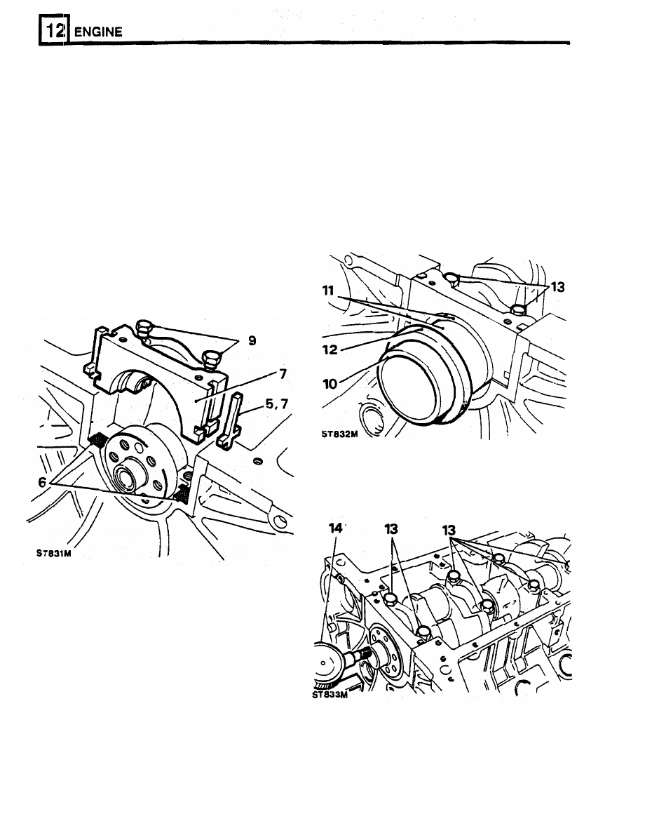
5. Fit
cross shaped side seals
to grooves each
assembly.
side of rear main bearing cap.
Do not cut side
Position oil seal,
lipped side towards the
seals,
they
must
protrude
1.5
mm
engine, o n to seal guide. Seal outside
approximately above bearing cap parting face.
diameter must
be clean and dry.
6.
Apply Hylomar SQ32M jointing compound to
rearmost half of rear main bearing cap parting
12. Push oil seal fully and squarely by hand into
face
or,
if
preferred, to equivalent area on
recess formed in cap and block until
it
cylinder block as illustrated.
contacts machined step
in recess.
7.
Lubricate bearing half and bearing cap side
Withdraw seal guide.
seals with clean engine oil.
8.
Carefully fit bearing cap assembly.
9.
Do not tighten fixings, but ensure that cap is
fully home and squarely seated on cylinder
block.
CAUTION: Do not handle oil seal lip, check
i t is not damaged and ensure that outside
diameter remains clean and dry.
10.
Position seal guide LRT-12-010 on crankshaft
flange.
11. Ensure that oil seal guide and crankshaft
guide and oil seal journal with clean engine
oil.
journal are scrupulously clean. Coat seal
CAUTION: Do not exceed 1,000 engine
rev/min for 15 seconds when first starting
engine, otherwise crankshaft rear oil seal
will be damaged.
13. Tighten cap bolts
to
correct torque, numbers
one
to four bearings
70
Nm, rear main
bearing
90
Nm.
14. Check crankshaft end-float, 0.10
to 0.20 mm.
ST834M
ENGINE
FIT CONNECTING
RODS
AND PISTONS
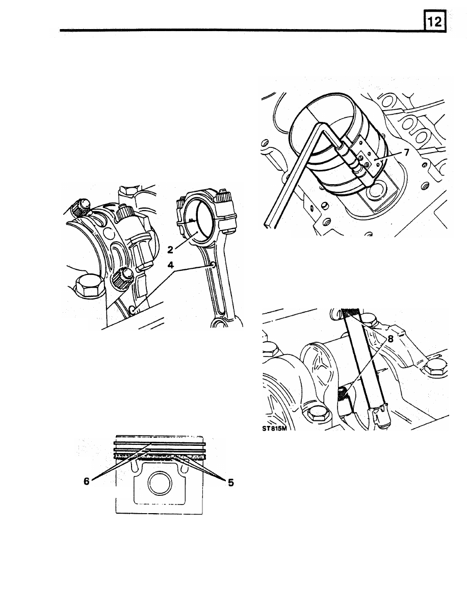
7 .
Using a piston ring compressor, locate piston
into cylinder bore, until piston crown
IS
just
below cylinder block top face.
1.
Locate applicable crankshaft journal at
B.D.C.
2,
Place bearing upper shell in connecting rod.
3.
Retain upper shell by screwing guide bolts
605351
onto connecting rods.
4.
Insert connecting rod and piston assembly into
respective bore, noting that domed shape
boss on connecting rod must face towards
front
of engine on right hand bank
of
cylinders
and towards rear on left hand bank. When
both connecting rods are fitted, bosses will
face inwards towards each other.
5.
Position oil control piston rings with ring gaps
all at one side, between piston pin and piston
thrust face. Space gaps in ring rails
approximately
25
mm
each side
of expander
ring joint.
6.
Position compression rings with ring gaps on
opposite sides of piston between piston pin
and piston thrust face.
9.
Place bearing lower shell in connecting rod
cap.
10.
Locate cap and shell onto connecting rod,
noting that rib on edge
of cap must be
towards front of engine on right hand bank of
cylinders and towards rear on left hand bank.
11.
Check that connecting rods move freely
sideways
on the
crankshaft.
Tightness
ST835M
indicates insufficient bearing clearance or
misaligned connecting rod.
I
ST836M
8.
Pull connecting rods
on to crankpins using the
guide bolts. Use extreme care
to
prevent
scratching crank pins.
ENGINE
RR1800E
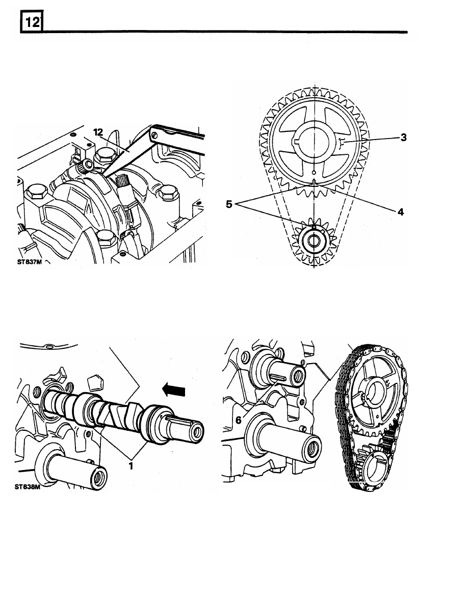
12.
Check end-float between connecting-rods on
5.
Encircle sprockets with chain keeping timing
each crankshaft journal. Clearance limits:
0.15
to
0.37
mm.
13.
Tighten connecting rod nuts
to
the correct
torque, 50 Nm.
Fit
oil strainer and joint
washer.
marks aligned.
FIT CAMSHAFT
TIMING CHAIN AND SPROCKET
6.
Fit sprocket assembly to camshaft and
crankshaft key locations. Check that camshaft
1.
Lubricate camshaft journals and carefully
key is parallel to shaft axis
to ensure
adequate lubrication
of
distributor drive gear.
insert camshaft into cylinder block.
2.
Turn crankshaft
to bring number one piston
to
TDC
.
3.
Temporarily fit camshaft sprocket with marking
' F or
'FRONT' outward.
4.
Turn camshaft until mark on camshaft
sprocket is at six o'clock position, remove
sprocket without disturbing camshaft.
RR1801E
Нет комментариевНе стесняйтесь поделиться с нами вашим ценным мнением.
Текст