Defender (1993+). Manual — part 72
STEERING
8
REISSUED:
FEB
1993
REISSUED:
FEB
1993
9
STEERING
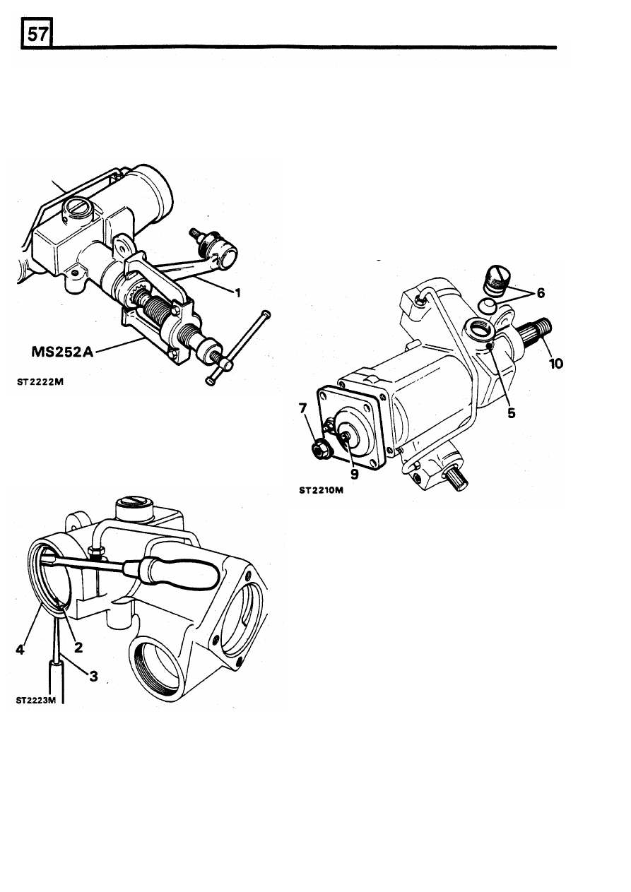
Dismantle
5.
Slacken the grub screw locking the rack pad
bring the steering
to
the straight ahead
6.
Remove the rack pad adjuster clockwise and
position and mark the relationship of the drop
withdraw the pad.
arm to the casing. Using special service tool
7.
Remove the sector shaft
lock
nut. The nut,
MS
252A
withdraw the drop arm and remove
which has a seal moulded inside it, also acts
the outer dust seal.
as a fluid seal. The nut should therefore be
discarded and a replacement new nut
obtained for reassembly.
8.
Remove the sector shaft cover bolts.
9. Turn the sector shaft adjuster clockwise with a
6 mm Allen key whilst holding the cover, to
prevent it turning, until the cover is removed.
10.
The sector shaft can now be removed from
the casing.
1.
To
assist assembly, turn the input shaft
to
adjuster.
2.
Rotate the piston cover retaining ring until one
end is about 12 mm
from
the extractor hole in
the side of the cylinder housing.
3. Lever the retaining ring from its locating
groove by inserting a suitable pointed drift
through the extractor hole. Complete the
removal of the ring using a screw driver.
4.
To
remove the cover, turn the input shaft, in
the appropriate direction, until the piston
pushes out the cover. For a left-hand steering
box, position the sector shaft on the left-hand
lock and for a right-hand box on the
right-hand lock.
10
REISSUED: FEB
1993
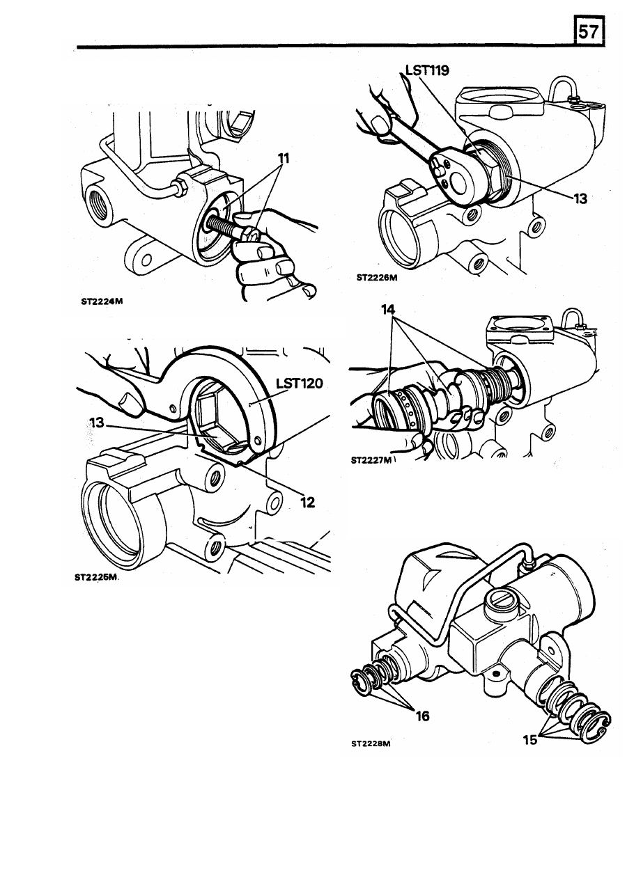
11.
To
remove the piston, screw a suitable bolt
into the piston crown and use it to pull the
piston from the casing.
STEERING
12.
Remove the worm shaft adjuster lock nut
using special service tool LST
120.
15.
Remove the circlip
from
the sector shaft bore
to enable the seal assembly to be withdrawn.
16.
Similarly, remove the circlip from the input
shaft (worm shaft) bore and remove and
discard the seals.
13.
Using service
tool
LST
119
remove the worm
shaft adjuster.
14.
To
withdraw the shaft and bearings
tap
the
splined end
of
the
shaft and lift-out the
assembly.
REISSUED:
FEB
1993
11
Нет комментариевНе стесняйтесь поделиться с нами вашим ценным мнением.
Текст