Defender (1993+). Manual — part 71
STEERING
41.
Fit the pedal box and secure with the six
bolts. Fit the pedal assembly mill board trim
and secure with retaining strip, vent cover and
screws.
42.
Fit the master cylinder
to
the servo and
connect the servo vacuum hose.
43.
Connect the stop lamp switch leads.
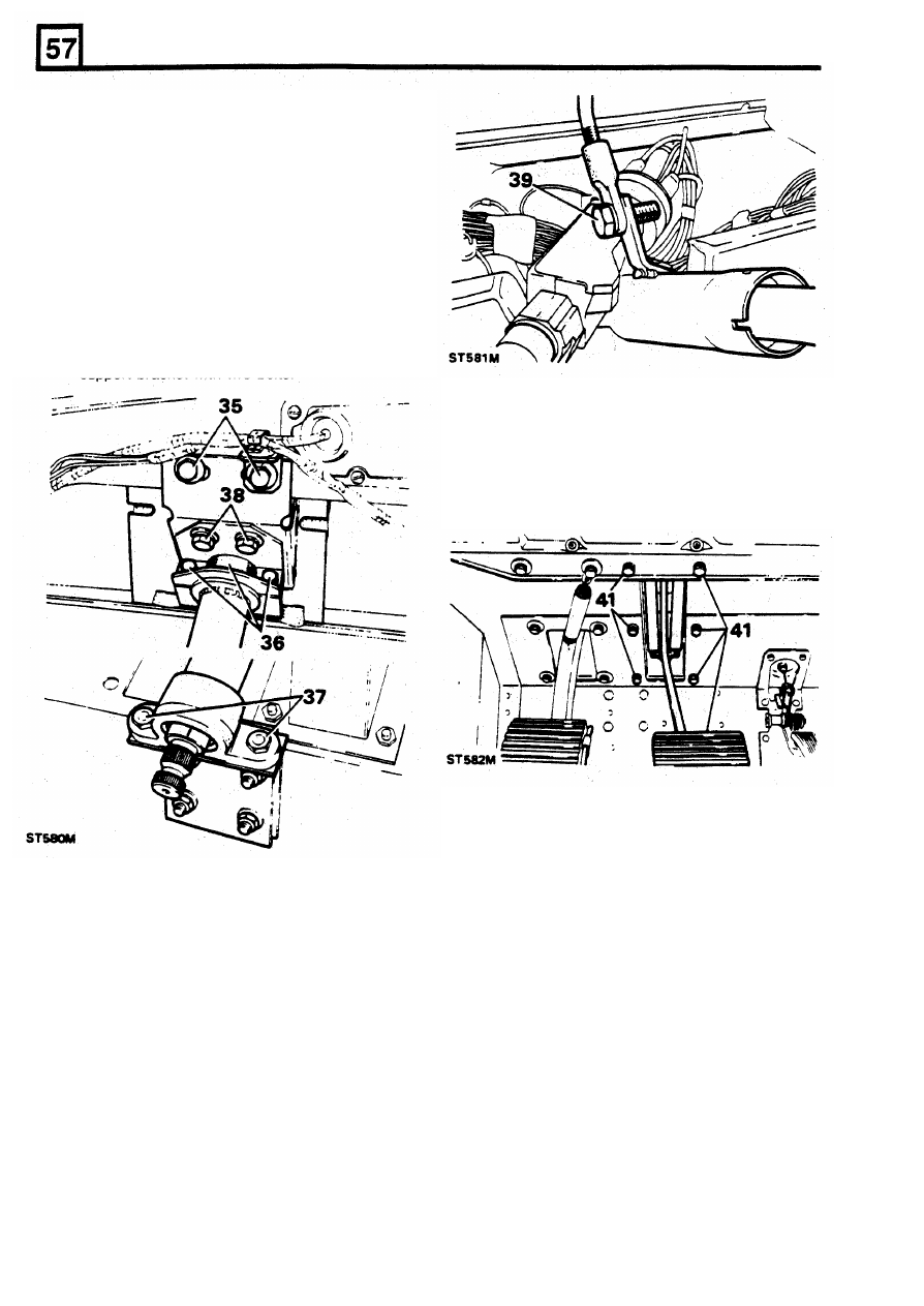
Fitting steering column
34. Fit the main support bracket and padding to
the steering column and manoeuvre the
column into position in the vehicle.
35.
Loosely secure the main support bracket and
harness bracket to the bulkhead with
two
bolts.
36.
Loosely fit the clamp and rubber packing strip
to the column and retain with two bolts.
37. Loosely secure the lower end
of
the column to
the lower support bracket with two nuts and
bolts.
38. Loosely secure the clamp bracket to the main
support bracket with two bolts.
Fit steering column
lock switch
44. Place lock switch
in
position and rotate the
steering column inner shaft to line
up
the slot
with the switch plunger.
39. Working inside the vehicle cab, fit the tie-bar
to the column bracket and secure with the
single bolt.
40. Finally tighten the main support bracket bolts,
clamp bracket bolts, upper clamp bolts and
the lower support bracket nuts and bolts.
4
REISSUED: FEB 1993
STEERING
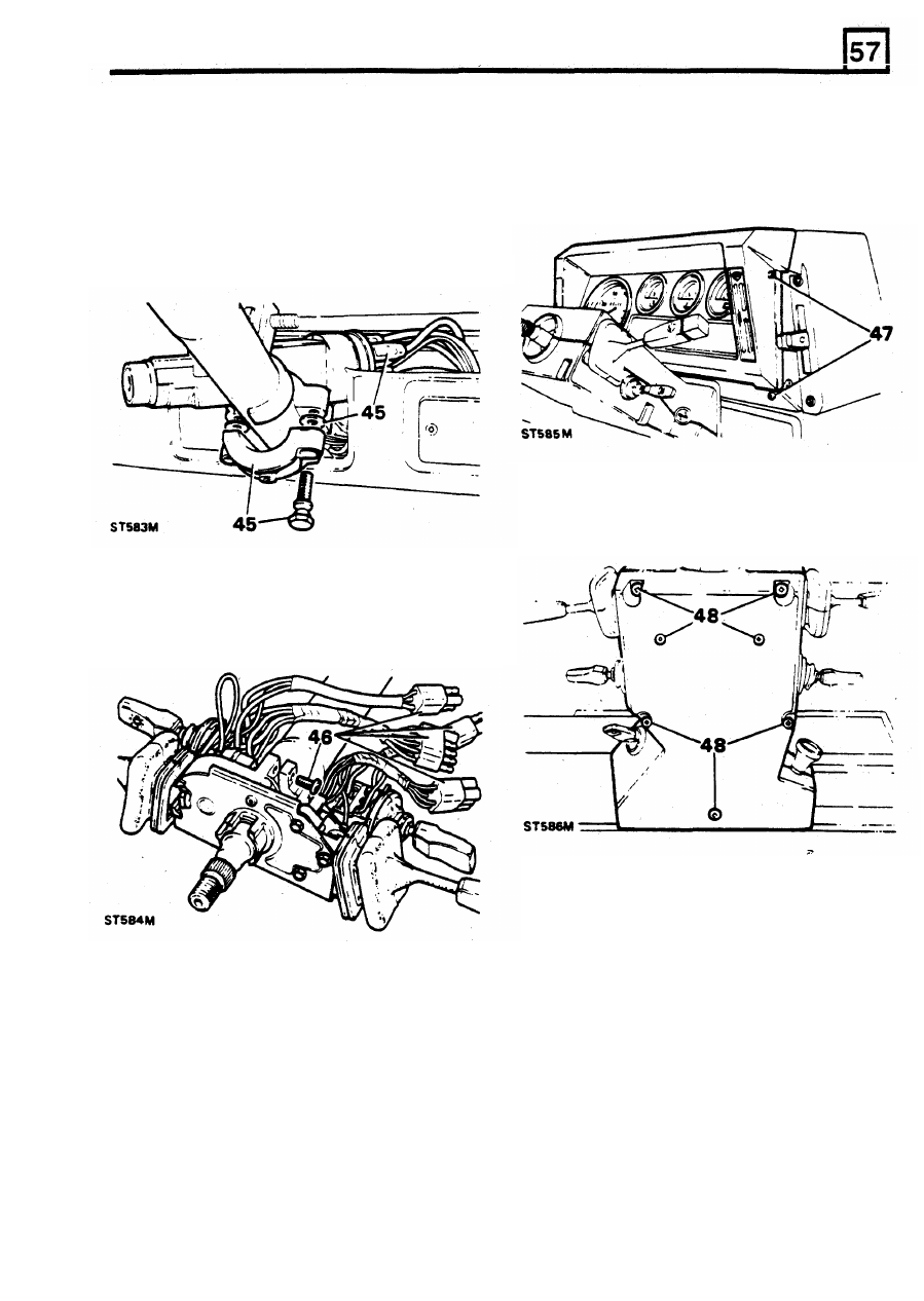
45.
Secure the lock to the column with the clamp
and shear bolts, whilst inserting two plain
washers between the switch and clamp.
47.
Offer up the instrument panel and connect the
Tighten the bolts but not enough to shear
speedometer cable, two block connectors one
them. Temporarily fit the steering wheel and
multi-plug and single white wire. Secure the
operate the switch and lock mechanism
panel with the four screws.
several times
to
ensure it functions properly
before finally tightening the bolts until the
heads shear. Connect the electrical leads to
the rear of the switch
Fit instrument panel and nacelle
48.
Locate the top half of the nacelle in position.
Locate the switch grommets and secure the
two
halves together with the four long screws
one short and
two
self-tapping screws.
Fit steering column switch assembly
46.
Fit the steering column switch assembly and
secure with the single screw. Connect the four
multi-plugs
to
the main harness.
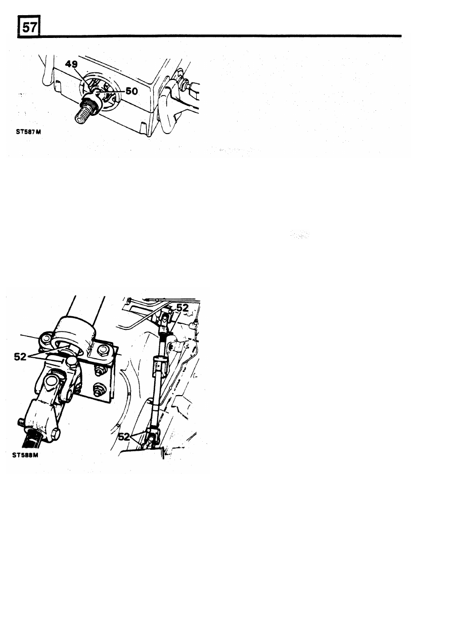
Fit the steering wheel
49.
Turn the cancelling ring
so
that the
slots
are
vertical and the lug with the arrow points to
the left, in the direction
of
the indicator switch.
Engage the steering lock.
50.
Fit the steering wheel with the finisher
attachment lug at the bottom. Ensure that the
indicator cancelling forks locate in the
cancelling ring
slots.
Secure the wheel with
the shake-proof washer and nut and tighten
to
the correct torque. Fit the finisher and secure
with the single screw.
REISSUED: FEB
1993
5
STEERING
Fit collapsible steering shaft
51.
If
necessary, fit new universal joints to the
support. Note that the long joint is fitted to the
short length of shaft and short joint
to
the long
end. The joints can only be fitted one way to
the shaft.
52. With the steering lock engaged and the road
wheels in the straight ahead position line-up
the marks made in instruction
2
and fit the
collapsible shaft assembly with the long leg of
the shaft to the steering box. Fit the pinch
bolts and tighten
to
the correct torque figure
22 - 28 Nm.
TORQUE
FIGURES
Nm
Drop arm nut
. . . . . . . . . . . . . . . . . . . . . . . . . . . . . . . . . .
176
Steering wheel nut
. . . . . . . . . . . . . . . . . . . . . . . . ..
3 8
Sector shaft cover to steering box
. . . . . . . . . . . . . . . . . . . . . . . . . ..
22
Top
cover
bolts
. . . . . . . . . . . . . . . . . . . . . . . . . . . . . . . . ...
50
Top cover bolts from serial
No:
lJ0001
. . . . . . . . . . . . . . . . . . . . . . . .
75
6
REISSUED: FEB
1993
STEERING
POWER
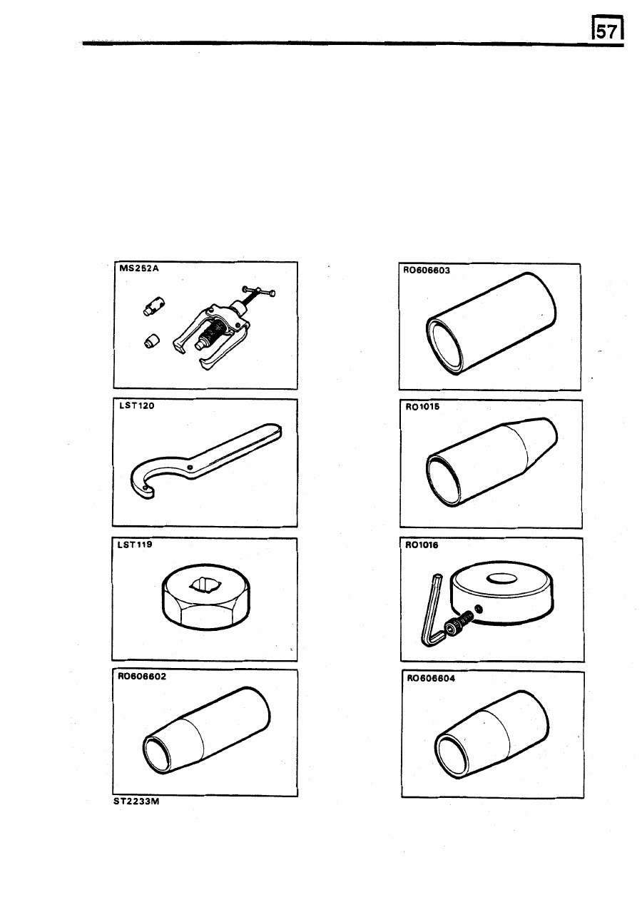
STEERING BOX OVERHAUL
Adwest Lightweight
Special service
tools
Drop
arm extractor
'C'
spanner
Worm adjusting socket
Ring expander
Ring
compressor
Torque setting tool
Seal saver, sector
shaft
M S 252A
/
LRT-57-012
LST 120
/
LRT-57-007
LST
119
/
LRT-57-006
RO
606602
/
LRT-57-019
RO
606603
/
LRT-57-020
RO
1016
/
LRT-57-017
RO
606604
/
LRT-57-021
Seal saver, valve and worm
RO
1015
/
LRT-57-016
7
REISSUED:
FEB
1993
Нет комментариевНе стесняйтесь поделиться с нами вашим ценным мнением.
Текст