Defender (1993+). Manual — part 73
STEERING
NOTE: The steering box has now been
2.
Check the condition of the adjuster thread and
dismantled except for the sector shaft bushes,
that there is no excessive vertical play. A
shown dotted. Since replacement bushes are not
movement of 2 mm
I
S
acceptable. Side play,
available, they should not
be
removed. The input
however, is of no significance.
shaft inner bearing cup and shims may also still
3.
Examine the bearing surfaces of the shaft for
be
i n position if jarring of the box has not
wear, scores and pitting.
already
dislodged them and instructions
for
4. Check the gear teeth for excessive or uneven
removing these appear later.
wear, scores and pitting.
5.
Examine the cover for damage and burrs.
INSPECTION
Remove and discard the seal. Check the bush
for wear and scores. Also check the adjuster
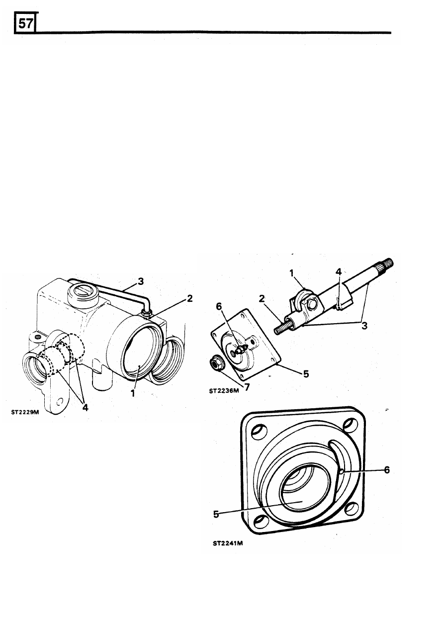
Steering
box casing
6.
Check the bleed nipple and threads and that
the bleed whole in the inside of the cover is
1.
Examine the piston bore for wear, scores and
pitting.
2.
Examine the inlet pipe thread in the side
of
the cylinder tube for damage and if necessary
NOTE: For replacement purposes, the cover,
repair using
a
suitable tap.
bush and seal are supplied as
a complete
cracks and dents and renew if in any way
faulty.
7.
The locknut, which should be discarded, also
4.
Since it is very unusual for the sector shaft
acts as a fluid seal and a new one should be
bushes to wear they are not available as
fitted on assembly.
replacements.
However,
they
should
nevertheless be checked for damage.
3.
Check the feed pipe for damage especially for
assembly.
Sector shaft and cover assembly
1.
Check that there
is
no side play on the roller.
If excessive play
does
exist the sector shaft
should be renewed likewise if any of the
following checks are unsatisfactory.
12
REISSUED:
FEB
1993
thread for damage
clear.
STEERING
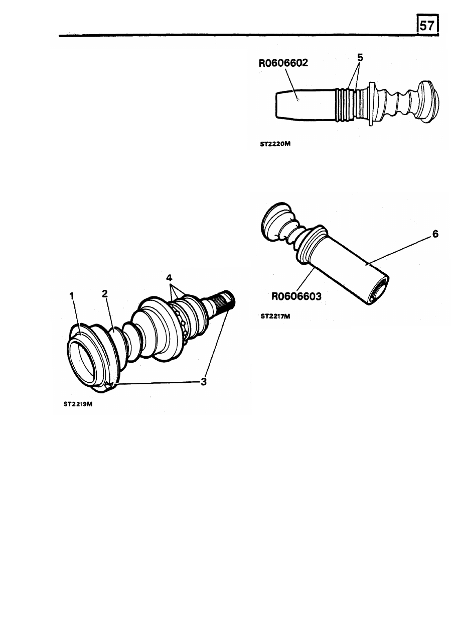
Valve and worm assembly
1.
Examine the bearing areas for wear. The
surfaces must be smooth and free from
indentations, scores and pitting.
2. Examine the worm for wear which must also
be smooth and free
of
scores
and
indentations.
3.
Check for any wear on the torsion bar
assembly pins. Grip the splined end of the
input shaft in a soft jawed vice and by hand
twist the worm end.
No
free movement should
exist between the input shaft and worm.
NOTE:
If
any wear does appear in the above
areas it is essential that a new valve and worm
assembly
is fitted.
6. Remove the expander tool and slide the
compressor tool
RO
606603
over the rings,
internal chamfered end leading and leave until
cool.
4.
Examine the valve rings which must be free
from cuts, scratches and grooves. The valve
rings must be a loose fit in the valve grooves.
If
any one
of
the rings is faulty,
all
the rings
must be renewed. Take care not to damage
the ring grooves when removing the rings.
5.
Fit replacement rings using expander tool
RO
606602. Expand the rings by immersing them
in hot water until pliable then carefully slide
the rings over the
tool,
from
the chamfered
end. Place the
tool
over the ring grooves and
slide the first ring into the groove nearest
to
the worm and
so
on until the third ring
is
in
place.
It
is important to fit the rings
in
this
sequence since the tool will not pass over the
rings.
REISSUED: FEB 1993
13
STEERING
2.
To
remove the inner bearing cup and shims
jar the casing on the work bench or use a
suitable extractor. Alternatively, if difficulty is
being
experienced,
warm
the
casing
universally
in
an oven or in boiling water.
Do
not, however, attempt to apply local heat since
distortion
of
the casing may result. Whilst the
casing is being heated, cool a suitable
mandrel
or
round bar
to
fit inside the bearing
cup. Insert the cooled bar
in
the heated
casing to retract the cup to enable it to be
withdrawn together with the shims which must
be
retained for reassembly.
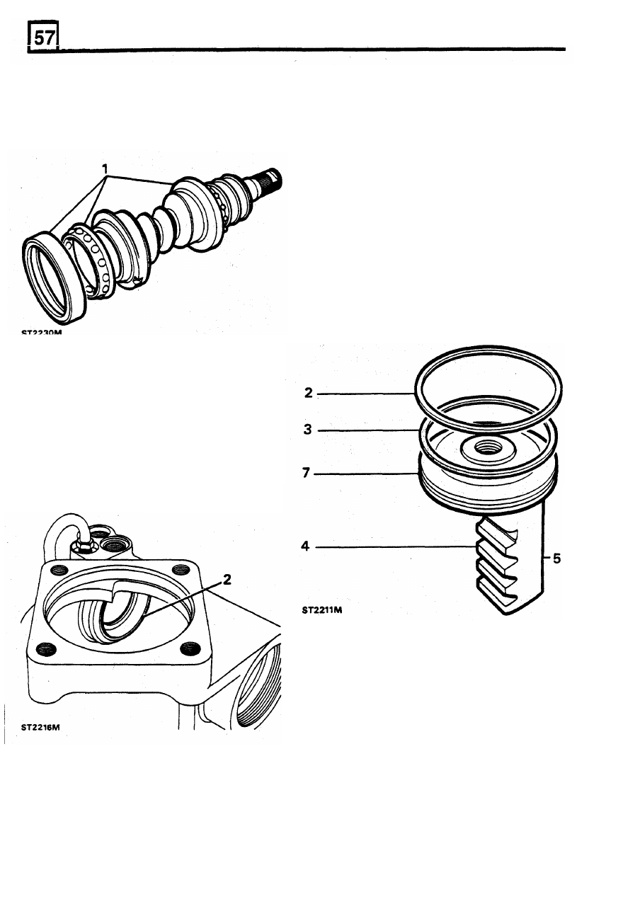
Ball bearing and cage assemblies
Rack and piston
NOTE:
That beneath the visible white Nylon ring
in
the piston groove, there is a rubber seal.
1.
Examine the valve and worm inner and outer
ball races and cups and if either is worn,
pitted or damaged in any way, both the cups
and the ball races must be renewed.
1.
Examine the outer seal and if worn or
damaged in any way it must be renewed
along with the rubber ring.
2.
Taking care not to damage the piston outer
diameter remove the plastic seal.
3. Likewise, carefully remove the rubber ring.
4. Examine the rack teeth
for
wear and damage.
5.
Check that the thrust pad bearing surface is
free
from wear and scores.
6. Check the piston outer diameters for burrs
and damage and repair as necessary using a
fine file and emery cloth.
7. Ensure that the bottom
of
the groove and the
inside walls are not damaged or burred.
Repair where necessary in the same way as
above
14
REISSUED:
FEB
1993
STEERING
8. Fit a new rubber ring to the piston groove.
ASSEMBLE
Warm a new white Nylon seal in hot water
and
fit
to the piston.
NOTE: When fitting replacement oil seals, these
9.
Immediately, whilst still warm, carefully insert
must
be lubricated, before fitting, with the
the piston squarely into the casing bore with
recommended steering
box fluid.
Also
ensure
the rack outwards, as illustrated, and leave
that absolute cleanliness is observed throughout
until cool.
the following assembly instructions.
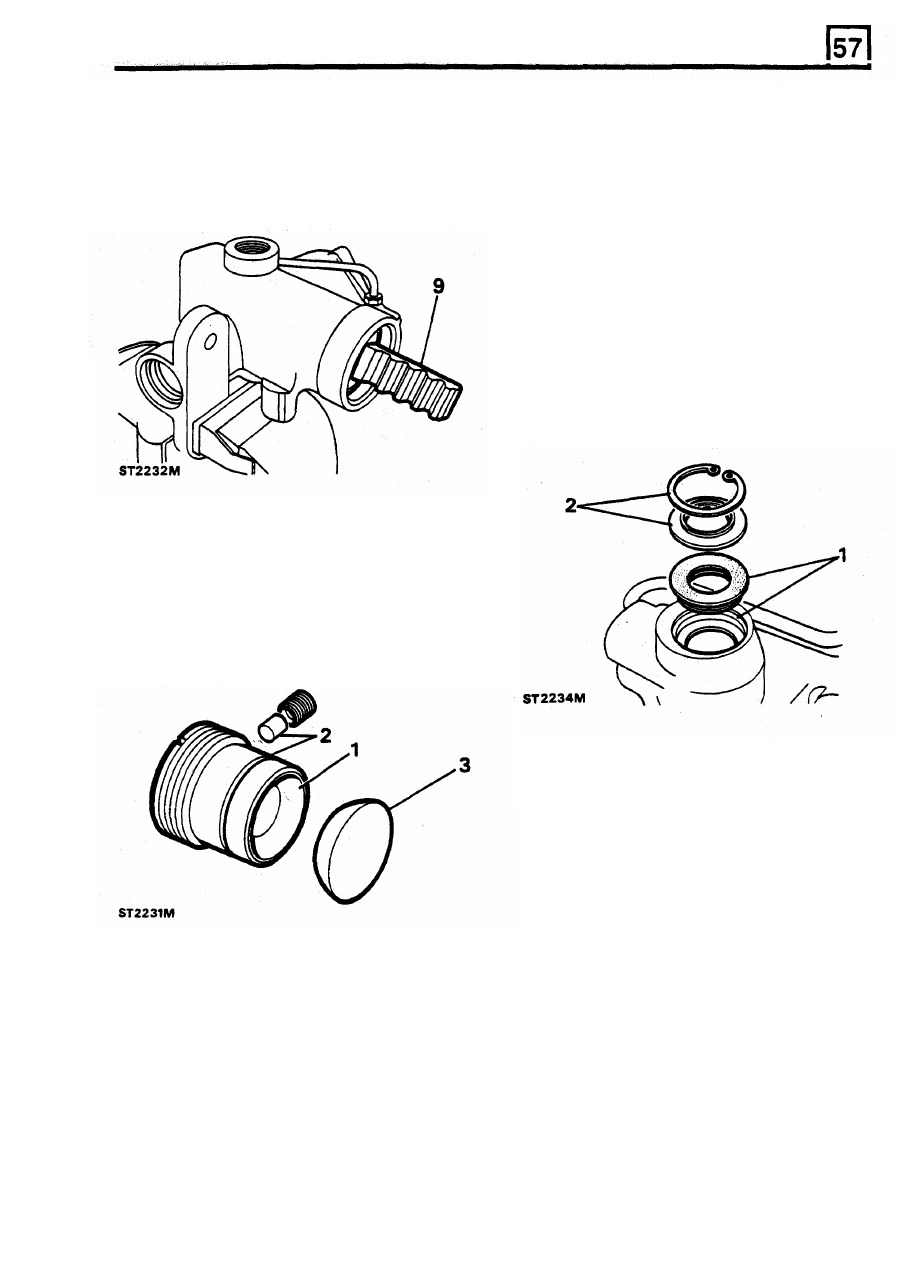
Fitting input shaft oil seal
1.
Fit a new seal, lipped side first, into the
housing noting that when correctly fitted the
seal backing will seat on the first shoulder in
the bore.
2.
Insert the extrusion washer
with
the flat side
downwards facing the seal. Secure the
assembly with the circlip and
to
ensure that it
is properly located, tap the circlip into the
groove with a punch.
Rack thrust pad and adjuster
1.
Examine the rack pad adjuster for general
condition particularly the pad bearing surface.
2.
Renew the seal and if necessary the nylon
thrust pad behind the grub screw.
3. Check the thrust pad for wear in particular the
flat side which slides on the reverse side of
the piston rack.
REISSUED:
FEB
1993
15
Нет комментариевНе стесняйтесь поделиться с нами вашим ценным мнением.
Текст