Defender (1993+). Manual — part 35
FUEL SYSTEM
REMOVING FUEL TANK AND FUEL PUMP
13.
Finally remove the tank
from
the
vehicle
DEFENDER 110
together with the fuel
pump
and
rear section
of the fuel feed
pipe.
Place tank
in
a
safe
Remove
area.
WARNING: Ensure fuel handling precautions
NOTE:
A
fuel vapour warning label must be
given
in
section
01
-
introduction regarding fuel
handling are strictly adhered
to
when carrying
14.
Disconnect the
rear
section
of
the
fuel
feed
out following instructions.
pipe from the pump.
15.
Remove the
five
retaining
screws
and
CAUTION: Before disconnecting any part
of
fuel
withdraw the fuel
pump
and sealing ring from
system it is imperative that all dust, dirt and
the tank.
debris is removed from around components to
16.
Cover the pump aperture in the tank
to
prevent ingress of foreign matter into fuel
prevent the ingress of foreign matter and
system.
escape
of
fuel vapours.
To
renew the pump, it
is
necessary
to
remove the
fuel tank from the vehicle.
attached to vehicle.
Refit
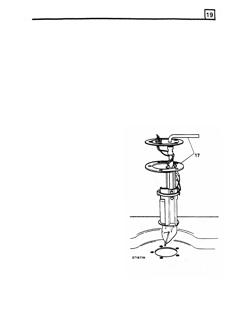
17.
Fit the pump into the tank with a
new
sealing
1.
Move the vehicle
to
a well ventilated area and
ring
so that the outlet pipe is directed towards
disconnect the battery. Clean the area around
the
front
of the vehicle and the electrical
the pump.
connections to the rear.
2.
Remove the fuel tank drain plug and allow the
fuel to drain into a suitable receptacle that can
be sealed afterwards
ENSURE TANK IS DRAINED COMPLETELY,
Refit drain plug
-
refer
to WARNING
concerning fuel handling at start
of
procedure.
3.
Working from the right hand side of the
vehicle, disconnect the fuel feed pipe and the
spill return at the rubber connections.
4.
Disconnect the fuel filler hose and breather
hose from the tank.
5. Whilst noting the cable colours, disconnect the
electrical leads from the fuel gauge unit at
the
left hand side
of
the vehicle.
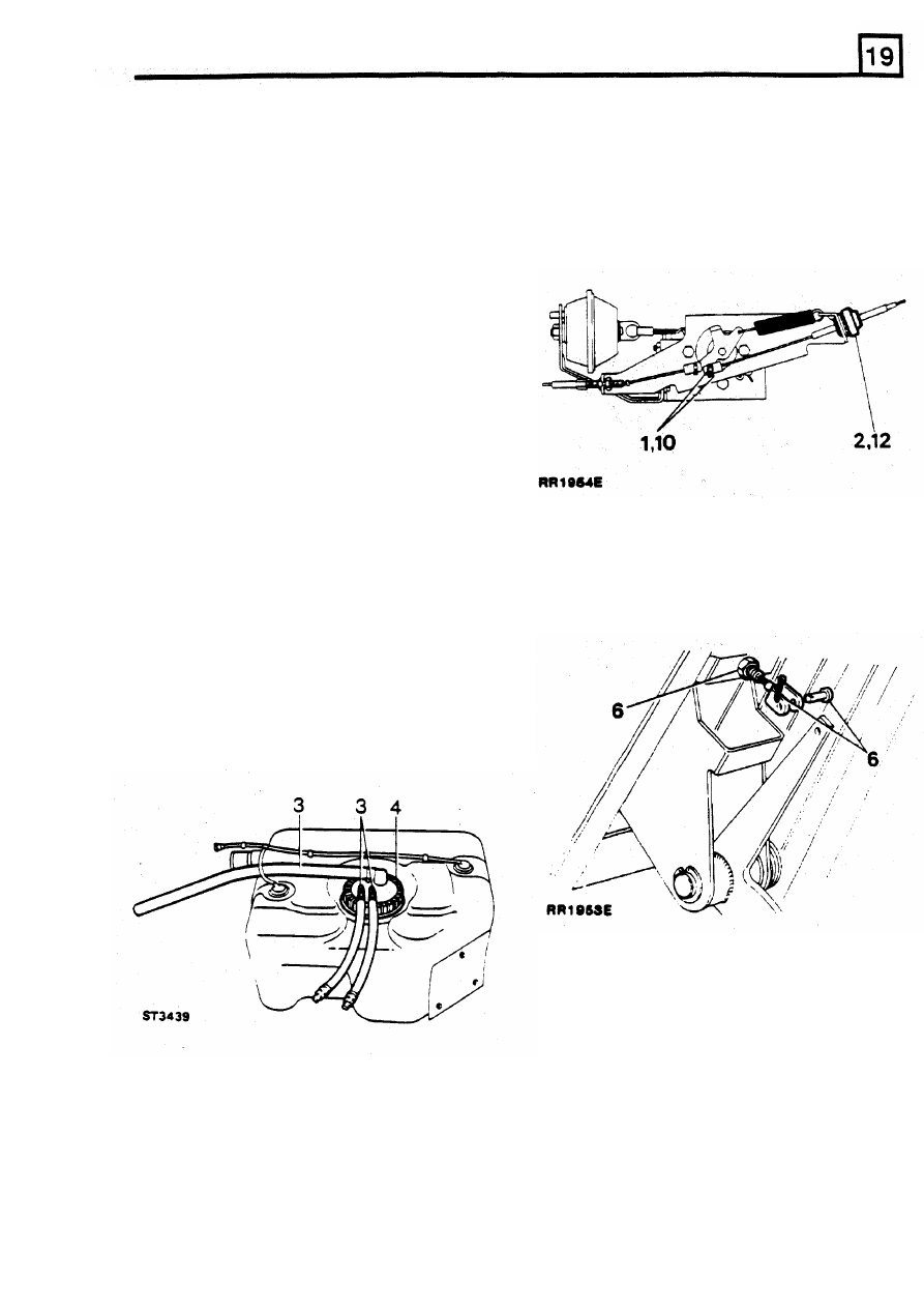
6.
Disconnect pipes to expansion tank.
7.
Remove the eight nuts and bolts securing
the
anti-roll bar
to the chassis and push the
anti-roll bar down
to
provide access to the
tank.
8.
Remove the left hand lashing eye to facilitate
removal of the fuel tank.
9.
Place a support under the fuel tank. preferably
one which will enable
the
fuel tank
lo
be
progressively lowered.
10.
Remove the
two nuts retaining
the
forward
end
of the tank.
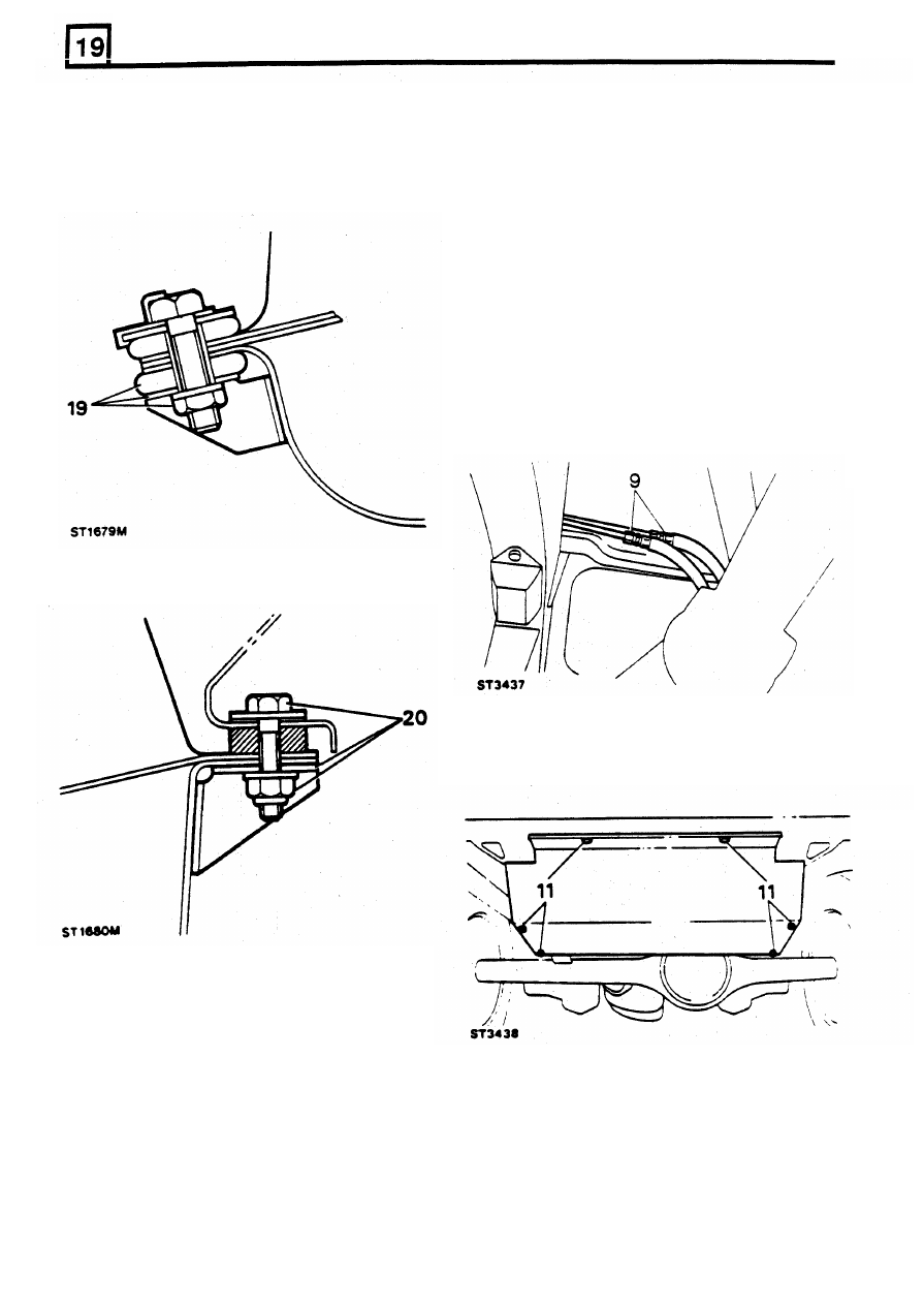
11
.
Remove the
two
nuts retaining the rear end of
the tank.
12.
Carefully lower the tank sufficiently to enable
the electrical leads to the fuel pump to be
disconnected.
RE-ISSUED: FEB
1993
21
FUEL SYSTEM
18.
Offer up tank to chassis ana connect the
electrical leads; black to ground
(-)
and white
to
positive
(+).
Remove
19.
Locate front
of
tank on the two captive bolts
and secure with the mounting rubber,
flat
and
WARNING: During the following operations
spring washers and nut.
ensure that the fuel handling precautions and
warnings
in
Section
1
of
this manual are being
adhered to.
FUEL TANK DEFENDER
90
1. Disconnect battery.
2. Raise vehicle onto axle stands.
3. Remove rear step.
4. Remove spare wheel.
5. Remove spare wheel carrier.
6. Drain fuel tank.
7. Disconnect fuel filler pipe at tank.
8. Disconnect breather pipe at filler neck.
9. Disconnect
main
fuel
lines
at
union
connections forward of tank.
20. Secure the rear
of the tankwith the
two
captive bolts, plain washer and Nyloc nut.
10.
Disconnect pipe to expansion tank using
11.
Loosen protection plate/fuel tank securing
special
tool LRT-19-002 on green connector.
bolts.
21
Connect the fuel teed and expansion tank
pipes.
22. Connect the spill return pipe.
23. Connect the fuel filler hose and breather pipe
to me tank.
24. Fit the left hand lashing eye.
12. Support tank and plate, remove securing
25. Fit the anti roll bar.
13. Lower tank sufficient to gain access and
26. Fit the drop plate support bars - if fitted.
27. Connect the fuel gage unit leads
disconnect multi-plug
28. Reconnect battery and check operation of
14
Complete lowering of tank and withdraw with
pump and changeover solenoid - if fitted.
29. Run engine check all connection for leaks.
bolts.
protection plate.
22
REVISED:
OCT
1993
FUEL SYSTEM
Refitting
REMOVING ACCELERATOR CABLE
15.
Position protection plate and fuel tank under
rear
of
vehicle.
Remove
16. Raise plate and tank sufficient
to
connect
1
Remove clevis pin securing accelerator cable
multi-plug.
to
lever.
17.
Complete raising and secure plate with bolts.
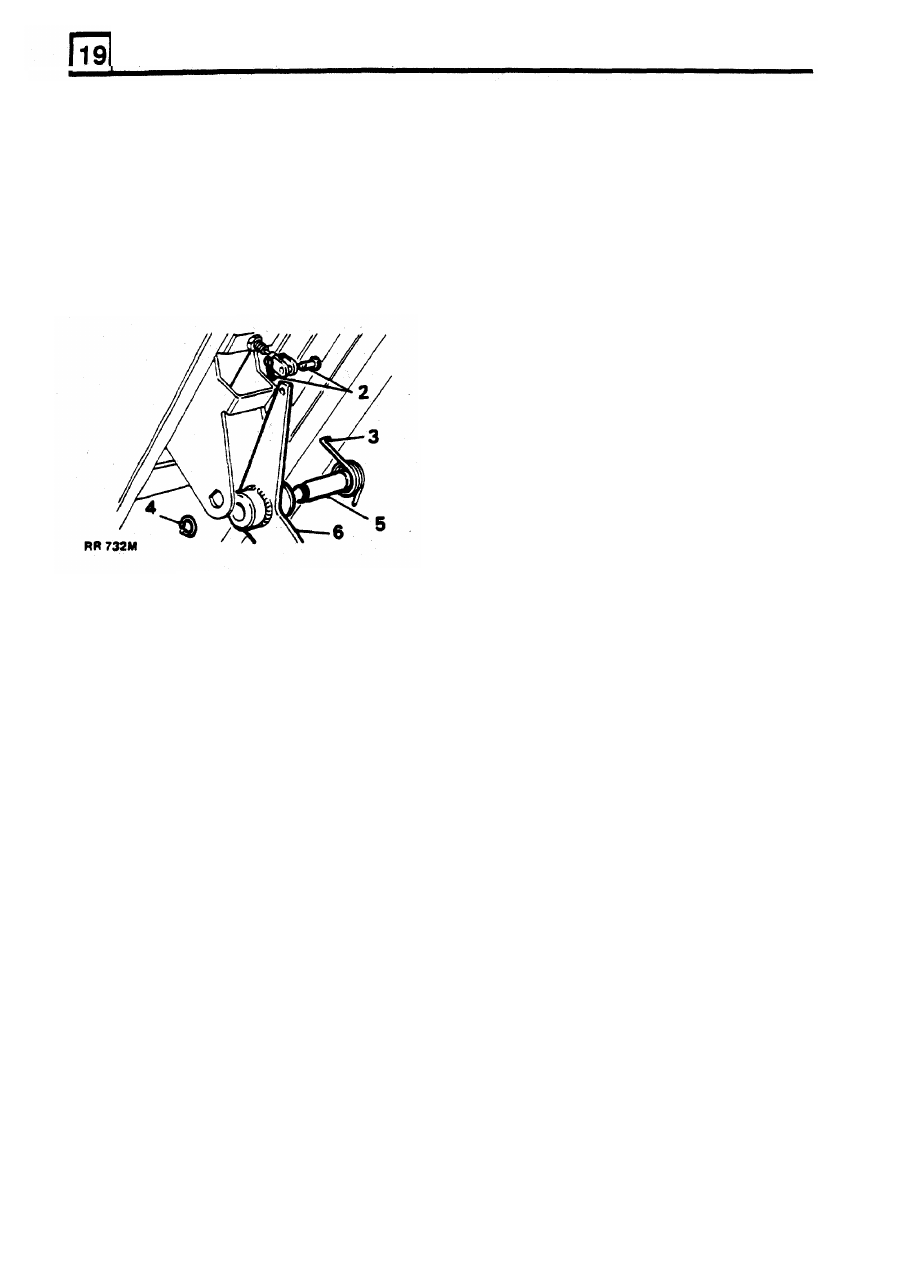
2.
Carefully pry accelerator cable adjustment nut
18. Connect all fuel and breather pipes at their
various locations/
3. Remove accelerator cable from mounting
19.
Refit spare wheel carrier.
bracket.
20. Refit spare wheel.
21. Refit rear step.
22. Remove vehicle from axle stands.
23. Replenish fuel tank.
24.
Reconnect battery.
25. Run engine for short period.
26. Check all disturbed connections for leaks.
out of mounting bracket.
FUEL PUMP/SENDER UNIT
Special tool
LRT-19-001 Fuel pump remover
Removal
WARNING:. During the following operations
ensure that the fuel handling precautions and
warnings in Section
1
of this manual are being
adhered to.
4.
Release outer cable from retaining clips in
engine compartment.
5. Remove
toe
board from drivers footwell.
6.
Disconnect cable from accelerator pedal and
release cable locknut.
7. Feed cable through bulkhead grommet into
engine compartment.
1. Disconnect battery.
2. Remove fuel tank.
3. Disconnect fuel and breather pipes from
pump/sender unit.
Refit
8. Feed new accelerator cable
from
engine
compartment through bulkhead grommet.
9. Connect cable
to
accelerator pedal.
10.
Connect cable
to accelerator linkage, using
a
new split pin.
11.
Clip outer cable adjustment nut into mounting
4.
Using special
tool
LRT-19-001 remove fuel
bracket.
12.
Adjust outer cable
to
give
1
57
mm
(0 062
in)
5.
Withdraw pump/sender unit from tank.
free play in inner cable Check
accelerator
operation.
pump retaining ring.
Refitting
6.
Refit in reverse order
to
removal.
REVISED: OCT
1993
23
FUEL
SYSTEM
REMOVING ACCELERATOR PEDAL
Remove
1.
Remove toe board from driver's footwell.
2.
Remove clevis pin securing throttle cable
to
accelerator pedal.
3.
Release tension
from
pedal return spring.
4.
Remove circlip from pedal pivot pin.
5.
Withdraw pivot pin.
6.
Remove accelerator pedal.
Refit
7.
Lightly grease pivot and clevis pins.
8.
Fit clevis pin using
a
new split pin.
9.
Reverse remaining removal instructions.
24
ADDITION:
OCT
1993
Нет комментариевНе стесняйтесь поделиться с нами вашим ценным мнением.
Текст