Defender (1993+). Manual — part 33
FUEL SYSTEM
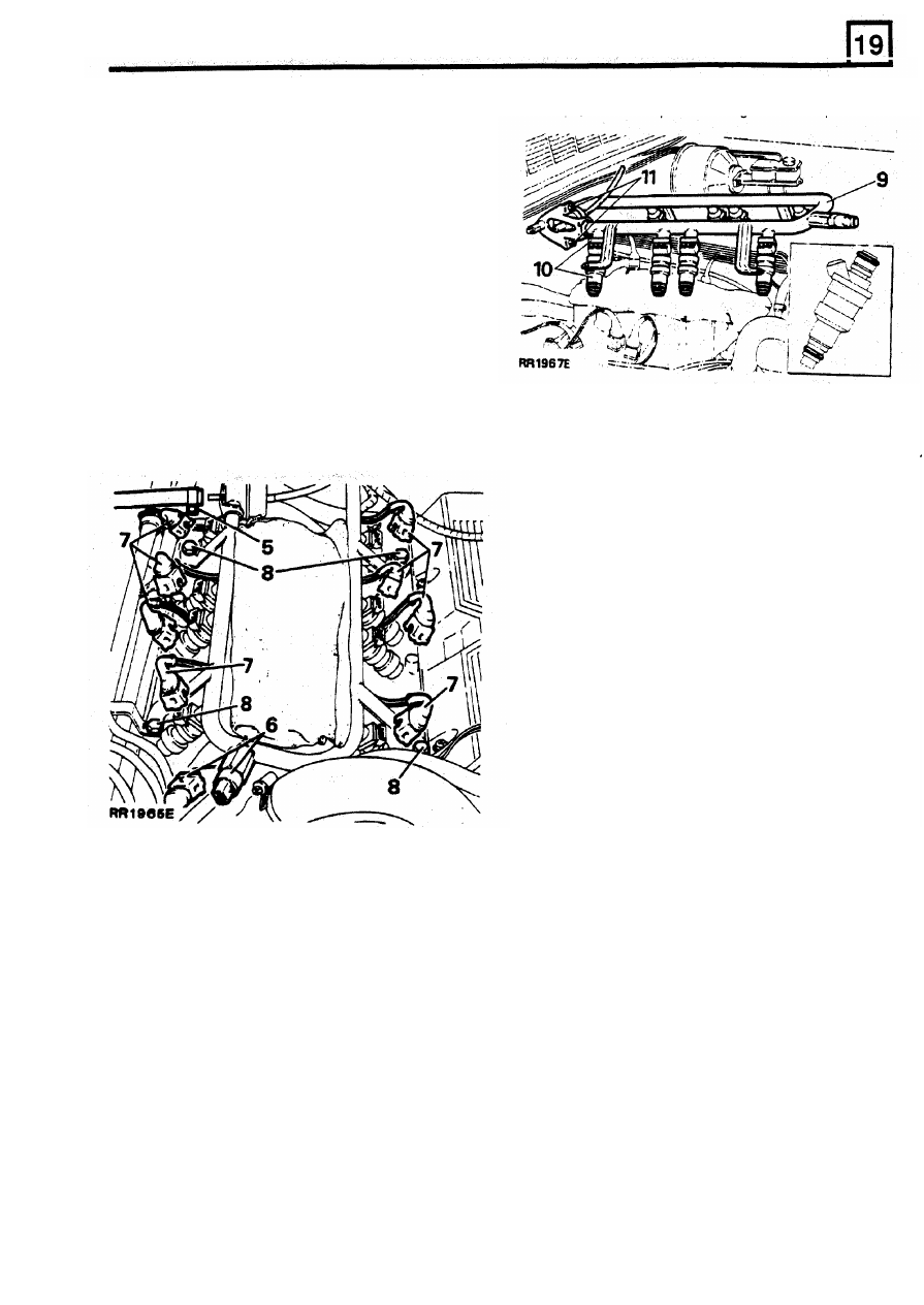
REMOVING FUEL RAIL-INJECTORS R/H AND L/H
To Remove
11. Remove fuel pressure regulator
if
required.
1.
Depressurise fuel system.
2.
Disconnect battery ground terminal.
3. Remove plenum chamber.
4. Remove ram housing.
NOTE: Place cloth over ram tube openings to
prevent ingress of
dirt.
5.
Release hose clamp and remove fuel return
hose from fuel pressure regulator.
6.
Disconnect multi-plug from engine fuel
temperature sensor.
7.
Disconnect multi-plugs from injectors.
To Refit
8.
Remove
five
bolts securing fuel rail support
brackets to intake manifold. Lay heater pipes
to one side.
12.
Fit
NEW
'0' rings, to injectors. Lightly coat
‘O’
rings with silicon grease 300. Insert injectors
into fuel rail, multi-plug connections facing
outwards.
13. Refit retaining clips.
CAUTION: Care must
be
taken when refitting the
fuel rail and injectors to intake manifold to
prevent damage to
'0' rings.
14. Fit a NEW
'O'
ring to fuel pressure regulator
lightly coat
'0' ring with silicon grease 300
and secure regulator to the fuel rail.
15.
Fit fuel rail and heater pipe assemblies to
intake manifold. Secure rail and pipes in
position
with
five bolts.
16. Reverse
removal
instructions
2 to
7.
17. Pressurise
fuel
system and check for fuel
leaks around injectors and fuel pressure
regulator.
9.
Remove fuel rail and injectors.
from rail.
10. Remove injector retaining clips, ease injectors
REISSUED FEB
1993
13
FUEL SYSTEM
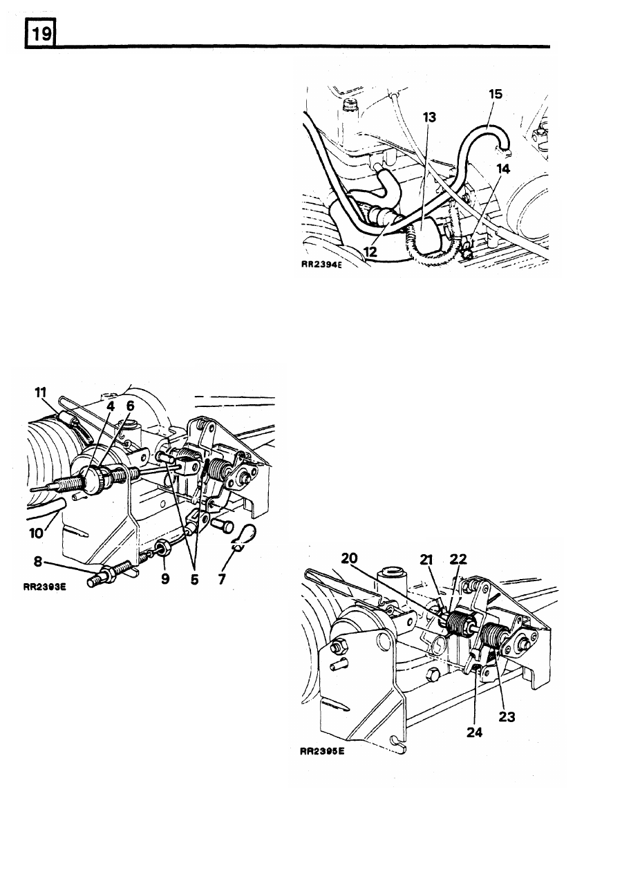
REMOVING PLENUM CHAMBER
Includes throttle levers and throttle disc
To Remove
1. Disconnect battery ground terminal.
2. Disconnect electrical multi-plug from idle
air
control valve.
3. Disconnect vacuum hose adjacent to idle air
control valve.
4.
Mark an identification line
on throttle cable
outer to assist re-assembly.
5.
Remove clevis pin from throttle cable.
6. Pry adjustment thumb wheel from throttle
bracket. Lay cable aside.
7.
Remove retaining clip and clevis bin from kick
down cable (automatic vehicles).
8. Apply adhesive tape behind rear adjustment
15. Remove distributor vacuum hose.
nut on kick down cable to prevent nut moving.
16. Release
two screws and remove throttle
9.
Remove front lock nut. Remove cable and lay
aside.
17. Remove six screws securing plenum chamber.
fitted).
18.
Remove
idle air control
valve
hose.
position sensor.
10. Remove cruise control vacuum hose (where
Remove plenum chamber.
Removing throttle lever assembly
19.
If
fitted
-
unclip cruise control actuator link.
Hold throttle fully open, release link from
countershaft assembly. Carefully return lever
assembly to close throttle.
20. Release tension on inboard throttle spring.
21. Bend back lock washer tabs.
22. Hold throttle stop lever
in closed position,
release nut from throttle shaft.
23. Release tension on outboard throttle spring.
24.
Remove overtravel spring.
11. Remove intake hose
from
neck
of plenum
chamber.
12. Disconnect throttle
position sensor multi-plug.
13. Remove PCV breather hose.
14.
Disconnect two coolant hoses and plug each
hose
to
prevent excessive loss of coolant.
Identify each hose for re-assembly.
14
REISSUED:
FEB 1993
FUEL
SYSTEM
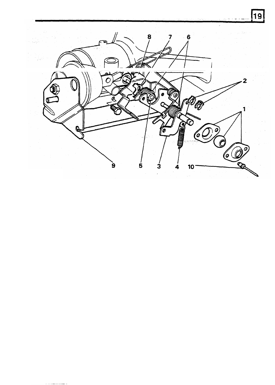
RR2406E
KEY
1.
Spherical bush/housing
2.
Retaining clips (2)
3.
Countershaft assembly
4.
Overtravel spring
5.
Throttle spindle nut
6.
Throttle return spring (2)
7.
Tab washer
8.
Throttle stop lever
9.
Throttle bracket assembly
10.
Pop rivets (2)
REISSUED:
FEB 1993
15
FUEL
SYSTEM
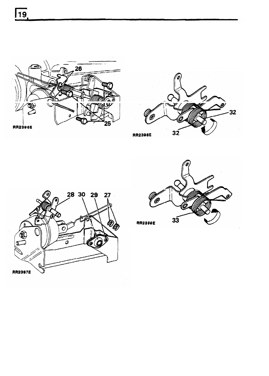
25.
Remove three
bolts
securing throttle bracket
31.
Grease new bush with Admax
L3
or
to
plenum chamber,
withdraw
bracket
Energrease
LS3.
Assemble bush into housing.
assembly
.
Assemble to throttle bracket using
two 4.7
mm
(3/16 in) diameter domed head rivets.
from throttle shaft.
32. Examine bearing surface of countershaft
assembly.
If
worn fit new assembly, otherwise
wind throttle return spring
off levers.
26. Remove tab washer and throttle stop lever
inspect
and
overhaul throttle lever assembly
33. Wind new spring onto countershaft assembly,
small hooked end
of spring is wound on first.
27.
Remove two retaining clips from spherical
bush.
28. Remove the countershaft assembly.
29.
If
spherical bush
is
worn, drill out
two
securing
rivets (4,7 mm, (3/16 in) diameter drill).
30.
Split assembly, discard worn bush.
34.
Grease shaft with
Admax L3 or Energrease
LS3,
fit
countershaft assembly
to
spherical
bearing, secure with
two
clips.
35. Examine throttle
stop lever for wear,
fit
a new
lever if necessary.
16
REISSUED: FEB 1993
Нет комментариевНе стесняйтесь поделиться с нами вашим ценным мнением.
Текст