Defender (1993+). Manual — part 32

FUEL SYSTEM
REMOVING
THROTTLE
POSITION SENSOR
To Remove
To Remove
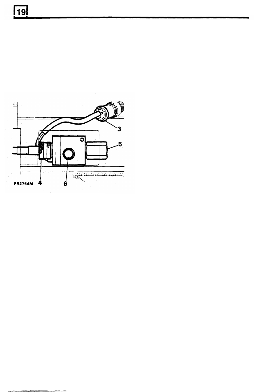
REMOVING IDLE AIR CONTROL VALVE
1.
Disconnect battery ground terminal.
1.
Disconnect battery ground terminal.
2.
Disconnect electrical plug.
2. Remove multi-plug.
3.
Remove
two
screws securing throttle position
3.
Unscrew idle air control valve from rear
sensor to plenum chamber and carefully pull
plenum chamber.
throttle position sensor
off throttle shaft.
4.
Remove washer.
4.
Remove old gasket.
To Refit
5.
Fit new gasket.
6.
Align throttle position sensor and shaft fiats,
slide switch
on
to
throttle shaft. Secure throttle
position sensor to plenum chamber.
To Refit
5. Fit
NEW sealing washer.
CAUTION: D O NOT operate throttle mechanism
while throttle position sensor is loosely fitted,
NOTE: If same idle air control valve is being
damage may be caused to throttle position
refitted clean sealing compounds from threads.
sensor wiper track.
Apply Loctite 241 to threads of idle air control
valve before reassembly.
6. Tighten idle air control valve to 20 Nm.
7. Reverse removal instructions.
REISSUED:
FEB
1993
9
FUEL
SYSTEM
REMOVING VEHICLE SPEED SENSOR
REMOVING FUEL INJECTION-RELAY MODULES
To Remove
Incorporated in fuel injection electrical system are
two
relays modules and a diagnostic plug. Access
to
the modules and plug is gained by removing the toe
board from the front passenger’s footwell. For exact
location, refer to illustration ST 3362M in Electrical
1.
Place vehicle on ramp, apply parking brake.
2.
Disconnect battery ground terminal
.
3.
Raise ramp, disconnect electrical plug.
4.
Disconnect speedometer cable.
Section 86.
5.
Do not remove blanking cap.
6.
Remove single bolt. Remove vehicle speed
REMOVING ELECTRONIC CONTROL MODULE
NOTE: The ECM is not serviceable, in event of
module failure
it
must be replaced.
To Remove
sensor from mounting bracket.
(ECM)
-
14
CUX
1.
Disconnect battery ground terminal.
2.
Remove toe board from front passenger’s
footwell.
3.
Release ECM plug retaining clip.
4.
Detach plug from ECM.
5.
Remove securing screws and withdraw
ECM.
To Refit
6.
Refit ECM by reversing the removal
procedure.
To Refit
7. Reverse the removal instructions.
10
REISSUED:
FEB
1993
FUEL SYSTEM
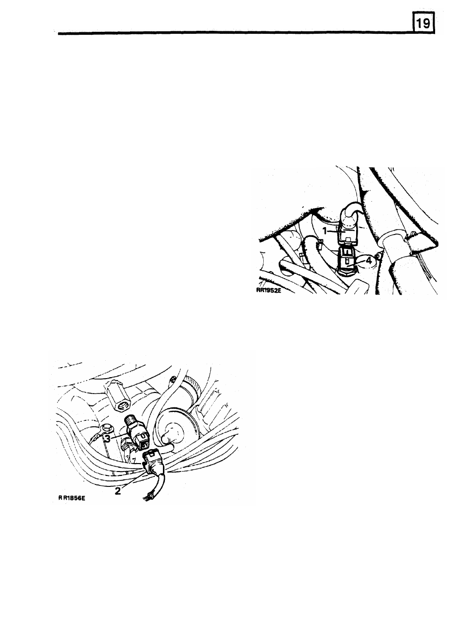
REMOVING INERTIA FUEL SHUT-OFF SWITCH
REMOVING ENGINE COOLANT TEMPERATURE
The inertia fuel shut
off switch is located
adjacent to the auxiliary fuse panel. Access
is
gained by removing the fuse panel cover.
To Remove
multi-plug.
SENSOR
To Remove
1.
Disconnect engine coolant temperature sensor
1.
Disconnect battery ground terminal
.
2.
Release radiator bottom hose, partially drain
2.
Remove
two
screws securing inertia fuel
cooling system.
3.
Withdraw inertia fuel shut-off switch and
4.
Remove engine coolant temperature sensor
shut-off switch.
3. Refit hose and tighten clamp.
disconnect multi-plug.
from left hand front branch of intake manifold.
5. Remove copper washer.
To Refit
4.
Reverse removal procedure. Ensure that
switch is reset (plunger in lowest position).
REMOVlNG
ENGINE
FUEL
TEMPERATURE
SENSOR
To Remove
NOTE: Fuel leakage will not occur when engine
fuel temperature sensor is removed from fuel rail,
therefore
it
is
not necessary
to depressurise the
fuel system.
1.
Disconnect battery ground terminal
.
To Refit
2. Remove multi-plug from engine fuel
temperature sensor
.
3.
Release engine fuel temperature sensor from
fuel feed rail.
tighten securely.
6.
Fit a NEW copper washer.
7.
Fit engine coolant temperature sensor and
8.
Refill cooling system.
9.
Run engine, check for water leaks around
engine coolant temperature sensor
.
To Refit
4.
Reverse removal procedure. Ensure engine
fuel temperature sensor is tightened securely
in
fuel rail.
REISSUED: FEB
1993
11
FUEL SYSTEM
DEPRESSURISING FUEL SYSTEM
WARNING: Under normal operating conditions
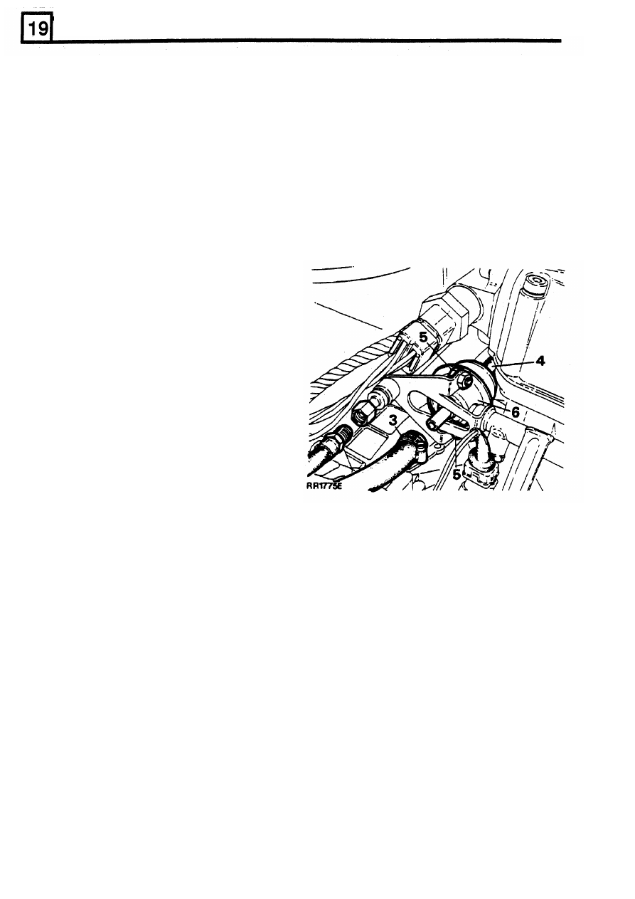
To Remove
the fuel injection system is pressurised by a high
pressure fuel pump, operating
at
up to
2.3
to 2.5
bar When
engine is stationary pressure
is
2. Disconnect battery ground terminal.
maintained
within
system.
To
prevent
3.
Release hose clamp securing fuel return hose
pressurised fuel escaping and to avoid personal
to
fuel pressure regulator. Remove the hose.
injury it i s necessary to depressurise fuel
4.
Pull vacuum hose from rear of fuel pressure
injection system before any service operations
regulator.
are carried out.
5. Remove
two
nuts and bolts securing fuel
pressure regulator to fuel rail, ease regulator
If
vehicle has not been run there will
be a small
fuel inlet pipe
out
of fuel rail.
amount of residual pressure in fuel line. The
6.
Withdraw fuel pressure regulator from engine
depressurising procedure must still
be carried
compartment.
out before disconnecting any component within
the fuel system.
The spilling of fuel is unavoidable during this
operation. Ensure that all necessary precautions
are taken to prevent fire and explosion.
REMOVING FUEL PRESSURE REGULATOR
1.
Depressurise fuel system.
1.
Remove fuel pump relay module.
2.
Start and run engine.
3.
When sufficient fuel has been used to cause
fuel line pressure to drop, injectors
will
become inoperative, resulting
in engine stall.
Switch
off ignition.
4.
Disconnect battery ground terminal
.
NOTE: Fuel at low pressure will remain in
system. To remove
low pressure fuel, place
absorbent cloth around fuel feed hose at fuel rail.
5. Disconnect either:
a) Nut and olive at fuel rail
OR
b) Hose at inlet end of fuel filter.
NOTE: Fit a
NEW ’0’ ring to fuel inlet pipe if
original fuel pressure regulator is refitted.
To
Refit
6.
Refit fuel feed hose.
7.
Refit fuel pump relay module, reconnect
7.
Lightly coat
‘0’
ring with silicon grease 300
before fitting fuel pressure regulator.
8. Crank engine (engine will fire
in approximately
8. Reverse removal procedure.
9.
Reconnect battery and pressurise fuel system.
Check there are no fuel leaks around fuel
pressure regulator connections.
battery.
6
to
8
seconds).
12
REISSUED:
FEB
1993
Нет комментариевНе стесняйтесь поделиться с нами вашим ценным мнением.
Текст