Defender (1993+). Manual — part 30
FUEL SYSTEM
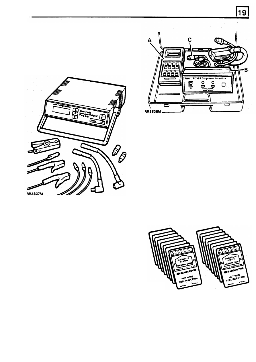
DIAGNOSTIC EQUIPMENT
IGNITION
Electronic Ignition Analsyer
Lucas Part No.
-
YWB 119
Supplied by Lucas Complete with instruction manual.
MEMORY CARDS
Land Rover Part Numbers include
two
memory
card and instruction manual in appropriate
language
Suitable for 14CUX ECU
ENGLISH
. . . . . .
RTC 6835
USA
. . . . . . . ..
RTC 6836
FRENCH
. . . . . ..
RTC 6837
GERMANY
. . . . ...
RTC 6838
ITALIAN
. . . . . ...
RTC 6839'
SPANISH
. . . . . .
RTC 6840
DUTCH
. . . . . .
RTC 6842
JAPANESE
. . . . ..
STC 127
LUCAS MFI DIAGNOSTIC EQUIPMENT
Complete kit Land Rover Part No. RTC 6834
Kit Comprises:-
A
Hand held tester
B
Interface unit
C
Foam lined carrying case
Serial link cable (Spare part Lucas
No. 54744753).
Memory cards are supplied separately
see
below
RR3838M
REISSUED: FEB
1993
1
FUEL SYSTEM
HOT WIRE MULTIPORT FUEL INJECTION
Engine fuel temperature sensor
Description
The engine fuel temperature sensor is located in the
fuel rail forward
of the ram housing. The engine fuel
The ’Hot Wire’ Multiport Fuel Injection system
temperature sensor sends fuel temperature data to
derives
its
name from the air flow meter which uses
the ECM, the ECM on receiving the data
will adjust
one cold wire and one electrically heated wire
to
the injector open time accordingly to produce good
measure the volume
of air entering the engine.
hot starting in high ambient temperatures.
The function of the system is to supply the exact
Idle air control valve
amount
of fuel directly into the inlet manifold
according
to the prevailing engine operating
The idle air control valve is screwed into a housing
conditions.
attached
to the rear of the plenum chamber, between
the plenum chamber and bulkhead. The idle air
To monitor these conditions, various sensors are
control valve has two windings which enable the
fitted
to
the engine to measure engine parameters.
motor to be energised
in
both directions thus
Data from the sensors is received by the Electronic
opening
or closing the idle air control valve as
Control Module (ECM), the ECM
will
then determine
required by the ECM.
the exact amount
of
fuel required at any condition.
The bypass valve will open and allow extra air into
the plenum chamber
to
maintain engine idle speed
The ECM having received data from the sensors
when the engine is under increased (Electrical and
produces pulses, the length
of which will determine
Mechanical) loads.
the simultaneous open time of each bank of injectors
The idle air control valve will control engine idle
in turn, which will govern the amount
of fuel injected.
speed when the vehicle
I
S
stationary.
Electronic control module - ECM
Heated oxygen sensors
The Multiport Fuel Injection system is controlled by
The two heated oxygen sensors are located forward
the ECM which is located behind the front
of the catalysts mounted
in the exhaust downpipes.
passenger’s toe board. The control unit is a
The sensors monitor the oxygen content of the
microprocessor
with
integrated
circuits
and
exhaust gases and provide feedback information
of
components mounted on printed circuit boards. The
the air/fuel ratio
to the ECM. Each heated oxygen
ECM is connected to the main harness by a
40
pin
sensor is heated by an electrical element
to
improve
plug.
its response time when the ignition is switched on.
Injectors
Fuel pressure regulator
The eight fuel injectors are fitted between the
The fuel pressure regulator is mounted in the fuel rail
pressurized fuel rail and inlet manifold. Each injector
at the rear of the plenum chamber. The regulator
is
comprises a solenoid operated needle valve with a
a mechanical device controlled by plenum chamber
movable plunger rigidly attached
to
the
nozzle valve.
vacuum,
it
ensures that fuel rail pressure is
When the solenoid is energized the plunger is
maintained at a constant pressure difference of
2.5
attracted off its seat and allows pressurized fuel into
bar above that of the manifold.
the intake manifold.
When pressure exceeds the regulator setting excess
fuel is returned to the fuel tank.
Engine coolant temperature sensor
Fuel pump
The engine coolant temperature sensor is located by
the front left hand branch
of the intake manifold. The
The electric fuel pump is located
in the fuel tank,
engine coolant temperature sensor provides engine
and is a self priming ‘wet’ pump, the motor is
coolant information to the ECM. The ECM on
immersed in the fuel
within
the tank.
receiving the signal from the engine coolant
temperature sensor
will
lengthen slightly the time that
the injectors are open, and reducing this time as the
engine reaches normal operating temperature.
2
REISSUED: FEB
1993
FUEL
SYSTEM
Mass air flow sensor
The hot-wire mass air flow sensor is mounted on a
It
should be noted that under high coolant
bracket attached
to
the left hand valance, rigidly
temperatures, when the engine is switched
off,
the
connected to the air cleaner and by hose
to the
condenser fans will be activated and will run for
plenum chamber inlet neck.
approximately ten minutes.
The mass air flow sensor consists of a cast alloy
body through which air flows. A proportion
of
this air
Vehicle speed sensor
flows through
a bypass
in
which
two
wire elements
are situated: one is a sensing wire and the other is a
The vehicle speed sensor is mounted on a bracket
Compensating wire. Under the control of an
located on the left hand chassis side member
electronic module which is mounted on the air flow
adjacent
to
the rear engine mounting. The vehicle
sensor body, a small current is passed through the
speed sensor provides road speed data
to
the ECM.
sensing wire
to
produce a heating effect. The
The ECM in turn detects vehicle movement from the
compensating wire is also connected to the module
road speed input and ensures that idle speed control
but is not heated, but reacts
to
the temperature of
mode is disengaged. Should the vehicle speed
the air taken in, as engine intake air passes over the
sensor fail in service the ECM idle speed control
wires
a cooling effect takes place.
would become erratic.
The electronic module monitors the reaction of the
The vehicle speed sensor also provides road speed
wires in proportion to the air stream and provides
data
to
the electric speedometer.
output signals in proportion
to
the air mass flow rate
which are compatible with the requirements of the
Inertia fuel shut off switch
ECM.
The inertia fuel shut off switch is
a
mechanically
Throttle
position
sensor
operated switch that is normally closed and is
connected to the fuel pump circuit. In the event of a
The throttle position sensor is mounted on the side
sudden impact the inertia fuel shut off switch opens,
of the plenum chamber inlet neck and is directly
and disconnects the electrical feed to the fuel pump.
coupled to the throttle butterfly shaft.
The inertia fuel shut off switch is reset by pressing
The throttle position sensor is a resistive device
down the button.
supplied with a voltage from the ECM. Movement of
the throttle pedal causes the throttle butterfly to
Relay modules
open, thus rotating the wiper arm within the throttle
position sensor which in turn varies the resistance in
Two multiport fuel injection relay modules are
proportion to the valve position. The ECM lengthens
located behind the front passenger toe board. The
the injector open time when it detects a change in
main relay module is energized via the ECM when
output voltage (rising) from the throttle position
the ignition is switched on and supplies current to
sensor.
the multiport fuel injection system. The fuel pump
In addition the ECM will weaken the mixture when it
relay module is energized by the ECM which in turn
detects the throttle position sensor output voltage is
operates the fuel pump to pressurize the fuel
decreasing under deceleration and will shorten the
system.
length of time the injectors are open.
When the throttle is fully open, the ECM will detect
the corresponding throttle position sensor voltage
and will apply full load enrichment. This is a fixed
percentage and is independent of temperature. Full
load enrichment is also achieved by adjusting the
length of the injector open time.
When the throttle is closed, overrun fuel cut off or
idle speed control may be facilitated dependant on
other inputs to the ECM.
The throttle position sensor is 'self adaptive', which
means that adjustment is not possible. It also means
the the throttle position sensor setting is not lost, for
example, when throttle stop wear occurs.
CAUTION: D o not attempt t o adjust throttle
position sensor.
Condenser fans
REISSUED:
FEB
1993
3
FUEL SYSTEM
ENGINE TUNING
MULTI METER CHECKS
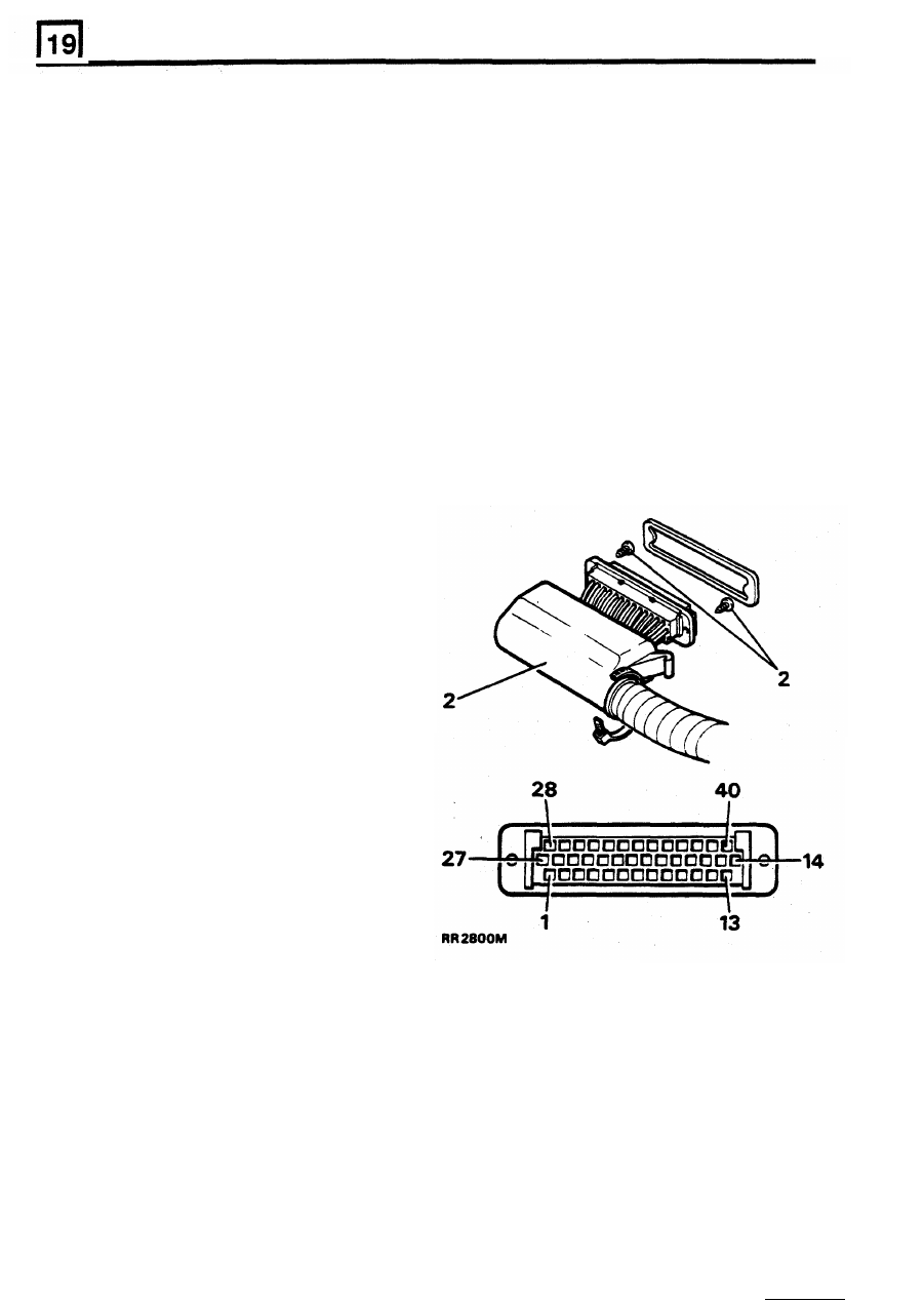
ECM - MFI circuit diagnosis
To carry out tests when 40 way multi-plug is
connected to the ECM,
it
is necessary to remove the
Circuit fault diagnosis may be carried out on all
MFI
two
screws securing the shroud to the plug to enable
vehicles, using a good quality Multi Meter or the
the multi-meter probes
to
be inserted into the back
of
hand held tester RTC6834. The tester displays the
the appropriate pin.
fault code and guides the operator by visual
prompts, through a series of diagnostic checks. Full
CAUTION: Tests requiring plug to be removed
operational and diagnosis instructions are provided
from ECM, must have meter probes inserted into
with the unit memory card.
back of plug. I f probes are inserted into plug
sockets, damage will occur to sockets resulting
Which ever instrument is used to diagnose the
i n poor connections when plug i s reconnected.
problem, the following Preliminary Checks must be
carried out first.
Testing
Preliminary checks
1.
Release harness plug from ECM.
CAUTION:
If
engine is misfiring or fails to start
within
12
seconds the cause must
be rectified.
Failure to do
so will result
in
irreparable damage
to the catalysts. After rectification the engine
are moulded onto rear of plug.
must
be run
at 1500
rev/min
(no
load) for 3
minutes to purge any accumulation of fuel
in
the
system.
1.
Check that the inertia fuel shut
off switch
is
not tripped.
2. Check fuse
D
in main fuse panel and the fuel
pump fuse in the auxiliary fusebox.
3.
Check
for ample fuel in tank.
4. Check air inlet system for possible leaks into
the inlet manifold.
5. Check
HT cables
for correct firing order and
routing.
2.
Remove plug shroud and manoeuvre
it
along
harness to enable meter probes to be inserted
into back
of plug.
3.
Only pin numbers
1,
13,
14,
27,
28
and 40
6.
Check ignition timing.
ETM A1.
Only when the above checks have been carried out,
should circuit diagnosis begin.
For diagnosis procedure using
a
Multi Meter
see
The diagnosis procedure using Hand Held Tester is
contained in the hand held tester manual.
View of plug - cover removed.
Pins 1 to 13 bottom row.
Pins 14 to 27 centre row.
Pins 28 to 40 top row. For clarity electrical leads
omitted.
For diagnostics using a multi meter, see ETM A1
.
4
REISSUED:
FEB
1993
Нет комментариевНе стесняйтесь поделиться с нами вашим ценным мнением.
Текст