Defender (1993+). Manual — part 92
AIR
CONDITIONING
(h) The compressor shaft must not be rotated
Evaporator
until the system is entirely assembled and
contains a charge of refrigerant.
Examine the refrigeration connections at the unit.
If
( j ) A new compressor contains an initial charge
of
the system should develop a fault, or
if
erratic
312,5 ml (11 UK fluid ozs) of oil when
operation is noticed, refer to the fault diagnosis
received, part
of
which
is
distributed
chart.
throughout the system when
it
has been run.
The compressor contains a holding charge of
gas when received which should be retained
until the hoses are connected.
component connected to the system to ensure
optimum dehydration and maximum moisture
protection of the system.
(I)
All
precautions must be taken to prevent
damage
to
fittings and connections. Slight
Stem type Service valves allow for the isolation
of
damage could cause a leak with the high
the compressor from other parts
of
the system,
pressures used in the system.
When these valves are used in conjunction with the
(m) Always use
two
spanners
of
the correct size,
liquid line quick-disconnect fittings, the three major
one on each hexagon, when releasing and
assemblies
of
the system can be removed from the
tightening refrigeration unions.
vehicle with a minimal
loss
of
refrigerant. In addition,
(n) Joints and ' O ' rings should be coated with
it
is
possible to remove major assemblies for repair
refrigeration oil to aid correct seating. Fittings
of
components which are not part of the refrigeration
which are not lubricated with refrigerant oil are
system,
or
provide access
to
parts
of
the vehicle
almost certain to leak.
which are obstructed by the air conditioning system,
(o) All lines must be
free of
kinks. The efficiency
without fully discharging the system. A thorough
of the system is reduced by a single kink
or
understanding
of
the stem type service valve is
restriction.
necessary before undertaking servicing
or
repair
(p) Flexible hoses should not
be
bent
to
a radius
less than ten times the diameter
of
the hoses.
(q) Flexible connections should not
be
within 50
mm
of
the exhaust manifold.
(r) Completed assemblies must be checked tor
refrigeration lines touching sheet metal panels.
Any direct contact
of
lines and
sheet
transmits
noise and must be eliminated.
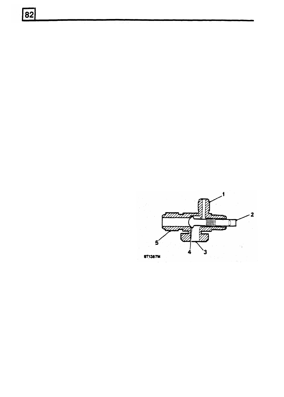
Service valves
There are
two
types of service valves in operation:
(k) The
receiver/drier
should be the last
'Stem' and 'Schrader'. To identify where the different
operations occur, stem type will be boxed.
Stem type
involving
the
air conditioning system.
PERIODIC MAINTENANCE
Routine servicing apart from visual checks, is not
necessary. The visual inspections are as follows:
Condenser
1
servlce port
With
a
hose pipe or air line.
clean
the
face of
the
2. Valve stem
condenser
to
remove flies. leaves etc. Check the
3 . Compressor
port
pipe connections
for
signs
of
oil leakage.
4.
Valve
seat
Compressor
5.
Hose connector
Check hose connections
for
signs of oil leakage.
Check flexible
hoses
for swelling. Examine the
compressor belt
for
tightness and condition.
Checking the compressor oil level and topping-up is
only necessary after charging the system
or
in the
event
of
a malfunction
of
the system.
Receiver/Drier
Stem type service valve
Examine the sight glass
for
bubbles with the system
operating. Check connections
for
leakage.
2
RE-ISSUED: FEB
1993
AIR
CONDITIONING
NOTE:
A
special wrench should be used to
adjust the valve to prevent damage to the stem.
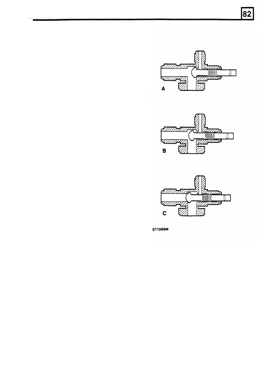
The stem type service valve has three positions, the
operation of which is explained as follows.
A. ON: FULLY ANTICLOCKWISE -
Normal
operating position, and the position which is
used for connecting and disconnecting the
manifold gauge set, is the on position. The
stem is turned fully anticlockwise. This seals
the service gauge port from receiving any
refrigerant flow.
B. MID (Test) POSITION -
After the service
gauge manifold has been installed (the valve
stem is in the on position), turn the valve stem
the required number of turns clockwise. This
will put the valve stem seat midway in the
service valve and allow full system operation
while permitting refrigerant pressure to reach
the gauges.
C. OFF: FULLY CLOCKWISE -
With the service
valve stem turned fully clockwise, the valve
will block passage of refrigerant flow through
the system. As illustrated, the refrigerant flow
to or from the compressor (depending on
whether it is high side or low side) is blocked.
WARNING: NEVER operate the air conditioning
system with the service valves in the
OFF
POSITION, it
will cause severe damage to the
compressor.
REISSUED:
FEB
1993
3
AIR
CONDITIONING
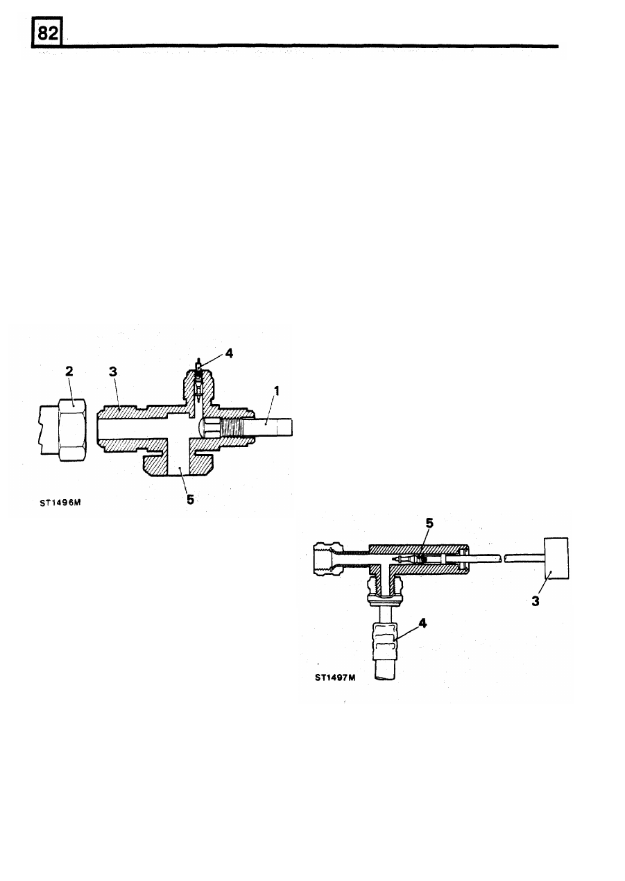
Schrader Type
B. OFF: FULLY CLOCKWISE -
With the service
valve stem turned fully clockwise, the valve
These are secured
to
the head of the compressor,
will block passage of refrigerant flow through
and the suction and discharge flexible end
the system. As illustrated, the refrigerant flow
connections are secured to them by unions.
to
or
from the compressor (depending on
The service valves are identified as suction or low
whether
it
is high side or low side) is blocked.
pressure, and discharge or high pressure. Whilst
they are identical in operation they are not
WARNING: NEVER operate the air conditioning
interchangeable, as the connections are of different
system with the service valves
in
the
OFF
sizes.
POSITION, it will cause severe damage
to
the
The valve with the larger connections fits the suction
side.
As the name suggests, these valves are for service
purposes,
providing
connections
to
external
pressure/vacuum gauges for test purposes. In
Where Schrader Valve depressors are not fitted to
combination with charging and testing equipment
the Testing equipment lines Valve core removers
they are used to charge the system with refrigerant.
Schrader service valve
compressor.
Valve Core Remover
can be used.
Valve Core Removal
The use of valve core removers will facilitate
servicing operations and should be used as follows:
1. Close all valves on the charging trolley.
2.
Remove the service valve cap and seals from
the valve core remover.
3.
Withdraw the plunger as far as possible and
connect the core remover to the service valve.
4.
Connect the hose to the core remover.
5. Depress the plunger until it contacts the valve
core. Unscrew the valve until it is free.
Withdraw the plunger to its full extent.
Service valve caps must be replaced when service
operations are completed. Failure to replace caps
could result in refrigerant
loss
and system failure.
1.
Valve stem
2. Hose connection
3. Service valve
4.
Schrader valve core
5 . Compressor port
NOTE: A special wrench
should be used to
adjust the valve to prevent damage to the stem.
The Schrader type service valve has
two
positions,
the operation of which is explained as follows
A. ON: FULLY ANTICLOCKWISE -
Normal
operating position, and the position which is
used for connecting and disconnecting the
manifold gauge set, is the on position. The
stem is turned fully anticlockwise. This seals
the service gauge port from receiving any
refrigerant flow.
4
REISSUED: FEB
1993
AIR CONDITIONING
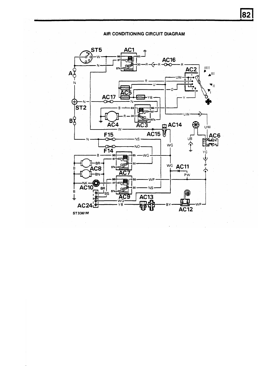
Key
to
Circuit Diagram
AC1.
System relay module
AC13.
Refrigerant pressure switches
AC2.
Evaporator/heater fan switch
AC14.
Engine coolant temperature switch
AC3.
Evaporator/heater fan relay module
AC15.
Diode
AC4.
Evaporator/heater fan
AC16.
Fuse in holder
-
30 amp
AC5.
Evap/heater fan speed resistor
AC17.
Fuse in holder
-
30 amp
AC6.
A/C on/off switch
AC24.
Connectors to
MFI
ECM
AC7.
Condenser fan relay
ST2.
Terminal post starter solenoid
AC8.
Condenser fans
ST5.
Starter/ignition switch
AC9.
Compressor relay module
B.
60 amp fuse, main fuse box
AC10.
Compressor
F14
20
amp fuse, main fuse box
AC11.
Diode
F15
5
amp fuse, dash fuse box
AC12.
Thermostat
REISSUED: FEB
1993
5
Нет комментариевНе стесняйтесь поделиться с нами вашим ценным мнением.
Текст