Toyota Sequoia (2005). Manual — part 285
F16988
GND
+BM
+BS
–
DIAGNOSTICS
ABS WITH EBD & BA & TRAC & VSC SYSTEM
DI–935
1129
INSPECTION PROCEDURE
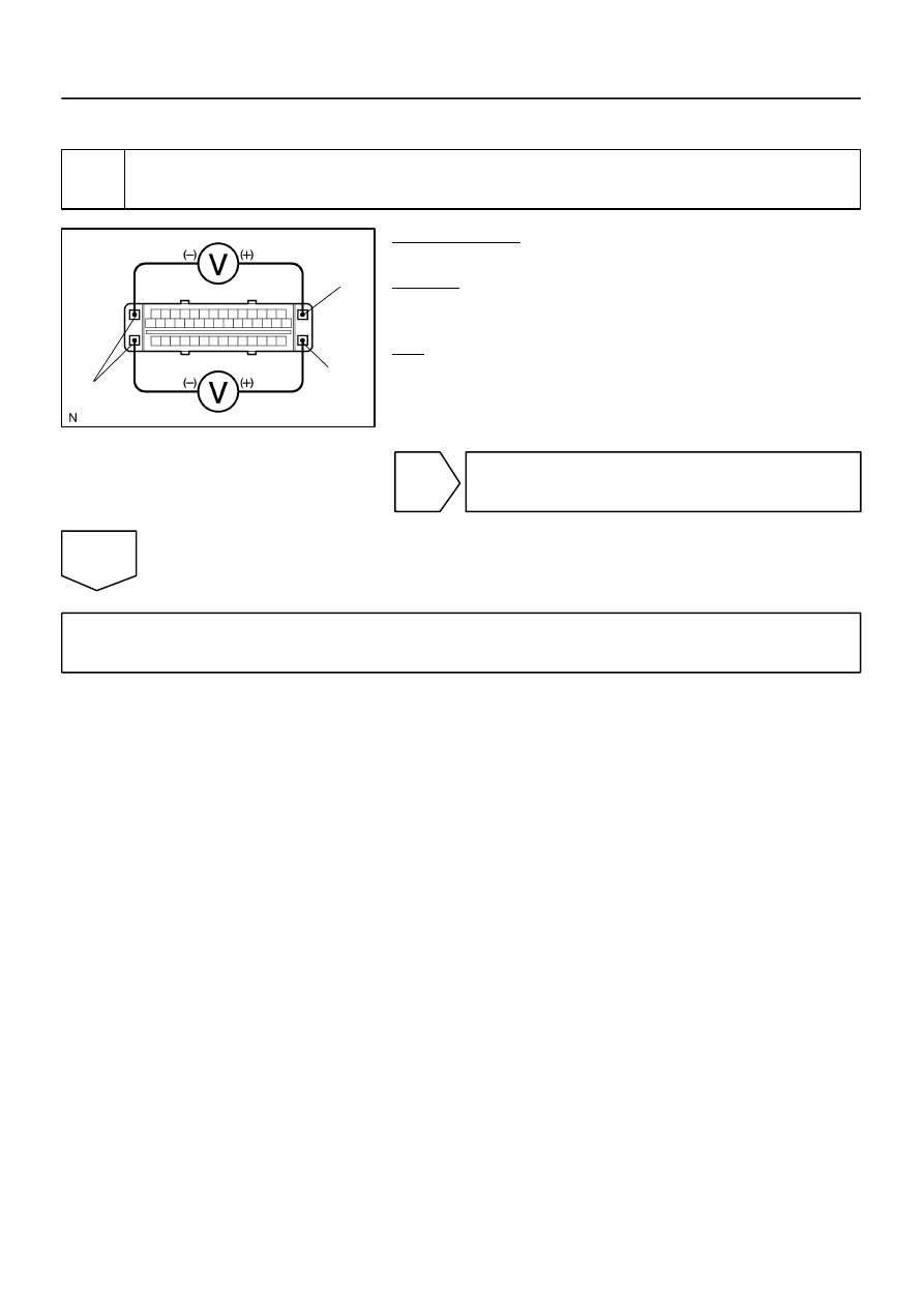
1
Check voltage between terminals +BS, +BM and GND of the skid control ECU
connector.
PREPARATION:
Disconnect the skid control ECU connector.
CHECK:
Measure the voltage between terminals +BS, +BM and GND of
the skid control ECU harness side connector.
OK:
Voltage: 10 to 14 V
NG
Check and replace ABS fuses.
Check and repair harness or connector.
OK
If the same code is still indicated after the DTC is deleted, check the condition of each connection.
If the connections are normal, the skid control ECU may be defective.
NOTICE:
When replacing the skid control ECU, perform the zero point calibration (See page
).
DI–936
–
DIAGNOSTICS
ABS WITH EBD & BA & TRAC & VSC SYSTEM
1130
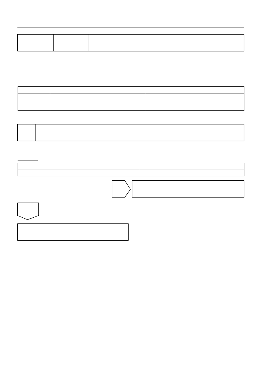
DTC
C1201 / 51 Engine Control System Malfunction
CIRCUIT DESCRIPTION
If trouble occurs in the engine control system, the ECM transmits the abnormality to the skid control ECU
via translate ECU. The skid control ECU sets this DTC and the skid control ECU prohibits TRAC and VSC
control.
DTC No.
DTC Detecting Condition
Trouble Area
C1201 / 51
Conditions 1. and 2. continue for 5 sec.:
1. Engine speed: 500 rpm or more.
2. A trouble signal of the engine control system is input.
Engine control system
INSPECTION PROCEDURE
1
Check engine control system.
CHECK:
Check engine control system (See page
).
RESULT:
DTC is not output
A
DTC is output
B
B
Check and repair engine control system
(See page
A
Replace ECM (See page
DIDM6–01

–
DIAGNOSTICS
ABS WITH EBD & BA & TRAC & VSC SYSTEM
DI–937
1131
DTC
C1202 / 52 Brake Fluid Warning Switch Circuit
CIRCUIT DESCRIPTION
The brake fluid level warning switch sends the appropriate signal to the skid control ECU when the brake
fluid level drops.
A brake fluid level signal is transmitted from the translate ECU to the skid control ECU.
DTC No.
DTC Detecting Condition
Trouble Area
C1202 / 52
When any of the following conditions are detected:
1. Low fluid level condition in the brake master cylinder
reservoir tank continues for 30 sec. or more when ve-
hicle stops, or for 60 sec. or more when driving.
2. With ECU terminal IG1 voltage is 9.5 V to 17.2 V and
open circuit for the brake fluid level warning switch cir-
cuit continues for 2 sec. or more.
Brake fluid level
Brake fluid level warning switch
Brake fluid level warning switch circuit
Skid control ECU
CAN1 communication system
Translate ECU
DIDM7–01
F19769
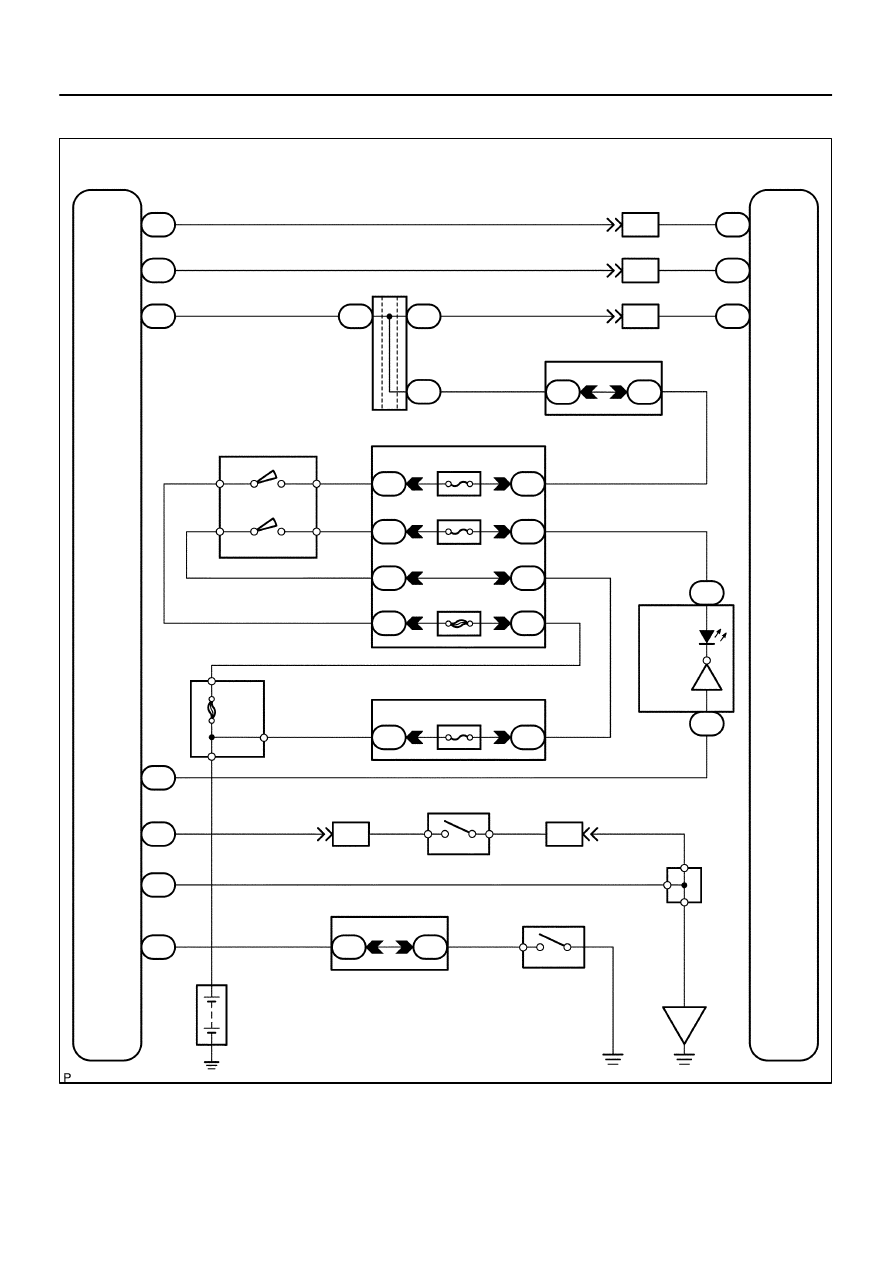
Translate ECU
VSC+
VSC–
IG1
7
T5
T5
11
1
T5
B–R
L
W
A
A
J37
J38
A
J37
B–R
J/C
B–R
B–R
L
W
7
IL2
6
IL2
1
IL1
6
S1
2
S1
13
S1
ABS &VSC Actuator
(Skid Control ECU)
CANH
CANL
IG1
8
3C
8
3A
B–R
Instrument Panel J/B
4
1C
2
1C
3
1C
6
1C
4
1F
11
1H
7
1J
1
1L
ECU–IG
IGN1
AM1
B–R
B–Y
W–R
W–L
B–O
W–R
W
1
2
Combination Meter
24 C6
Brake
1 C5
W
8
ALT
F10 Fusible
Link Block
Engine Room J/B
A
W–R
1
2D
1
2C
4
5
R–B
R–B
B1 Brake Fluid Level
Warning SW
Y–L
Y–L
W–B
23
IA1
1
2
9
IA5
O
A
A
O
O
J43
J/C
IG
Sub J/B No.4
LG–R
LG–R
4
4B
4
4D
1
P2 Parking
Brake SW
B
Battery
39
T5
24
T5
40
T5
4
T5
BRL
LVL2
GND
PKB2
Sub J/B No.3
I18
Ignition SW
AM1
IG1
AM2
IG2
1
5
W–L
2
6
AM2
B
B–R
(CAN1 Circuit)
(CAN1 Circuit)
DI–938
–
DIAGNOSTICS
ABS WITH EBD & BA & TRAC & VSC SYSTEM
1132
WIRING DIAGRAM
Нет комментариевНе стесняйтесь поделиться с нами вашим ценным мнением.
Текст