Toyota Sequoia (2005). Manual — part 284
W02871
–
DIAGNOSTICS
ABS WITH EBD & BA & TRAC & VSC SYSTEM
DI–931
1125
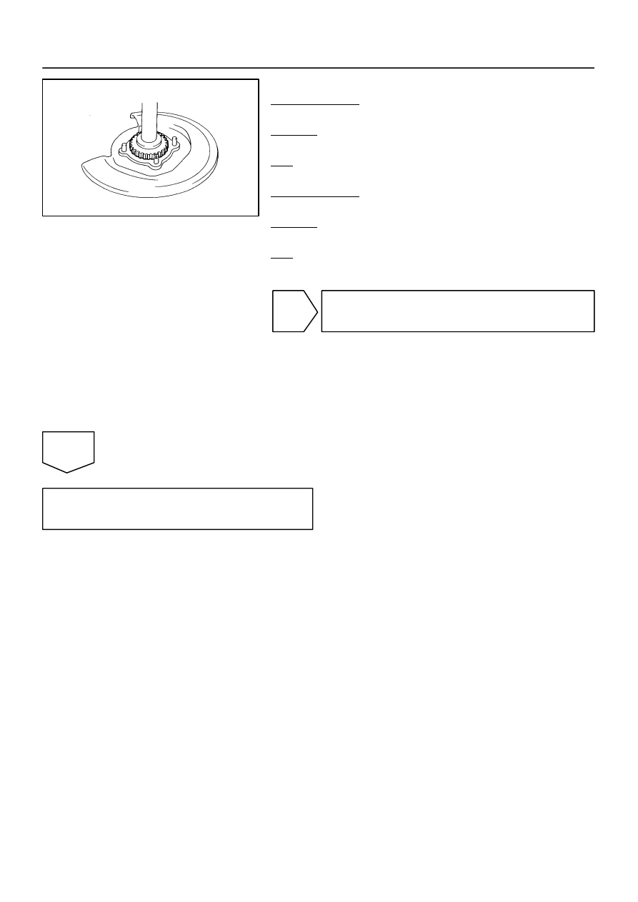
Rear:
PREPARATION:
Remove the axle shaft (See page
CHECK:
Check the sensor rotor serrations.
OK:
No scratches, missing teeth or foreign objects.
PREPARATION:
Remove the rear speed sensor (See page
CHECK:
Check the sensor tip.
OK:
No scratches or foreign objects on the sensor tip.
NG
Replace speed sensor or rotor.
NOTICE:
Check the speed sensor signal after replacement (See
page
HINT:
Remove any foreign matter if identified.
Check the output waveform again after reassembly.
OK
Replace skid control ECU
(See page
).
NOTICE:
When replacing the skid control ECU, perform the zero point calibration (See page
).
F19768
F10
Fusible Link Block
ABS
B
5
3
B–R
47
S1
W–B
17
IL1
W–B
1
S1
W–B
W–B
A
A
J18
J/C
Battery
IG
9
IL1
32
S1
+BS
GND2
ABS&VSC Actuator (Skid Control ECU)
IFL
IFR
IRL
IRR
OFL
OFR
ORL
ORR
ASR1
SV1
SV2
BATT
ASR2
GND1
Skid Control ECU
DI–932
–
DIAGNOSTICS
ABS WITH EBD & BA & TRAC & VSC SYSTEM
1126
DTC
C0226 / 21
ABS & VSC Solenoid Circuit
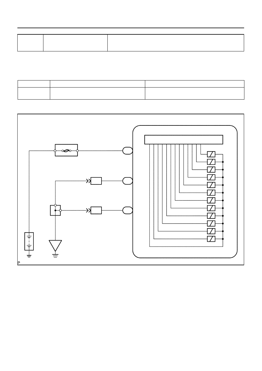
CIRCUIT DESCRIPTION
This solenoid turns on when signals are received from the ECU and controls the pressure acting on the wheel
cylinders to control braking force.
DTC No.
DTC Detecting Condition
Trouble Area
C0226 / 21
Solenoid valve signal does not match the check result.
ABS & VSC actuator
ABS & VSC solenoid circuit
WIRING DIAGRAM
DI93H–03
–
DIAGNOSTICS
ABS WITH EBD & BA & TRAC & VSC SYSTEM
DI–933
1127
INSPECTION PROCEDURE
1
Check DTC once more (See page
).
PREPARATION:
(a)
Clear the DTC.
(b)
Turn the ignition switch OFF.
CHECK:
Turn the ignition switch to the ON position, and check if the same DTC still remains in the memory.
RESULT:
DTC is output
A
DTC is not output
B
B
No problem.
A
Replace skid control ECU with actuator
(See page
).
NOTICE:
When replacing the skid control ECU, perform the zero point calibration (See page
).
F19782
Battery
16
S1
+BS
GND1
GND2
+BM
S1
S1
S1
47
1
32
B–R
B–R
W–B
W–B
W–B
W–B
5
B
F10
Fusible Link Block
ABS & VSC Actuator
(Skid Control ECU)
IG
J18
J/C
A
A
3
ABS
Motor Relay
Pump
Motor
IL1
17
IL1
9
DI–934
–
DIAGNOSTICS
ABS WITH EBD & BA & TRAC & VSC SYSTEM
1128
DTC
C0278 / 11
ABS & VSC Relay Circuit
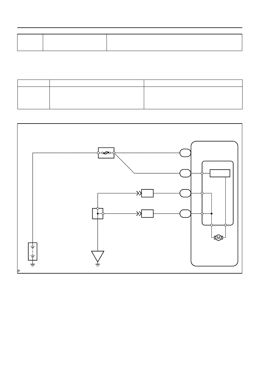
CIRCUIT DESCRIPTION
This relay supplies power to each ABS & VSC solenoid. If the initial check is OK, then the relay turns on after
the ignition switch is turned ON.
DTC No.
DTC Detecting Condition
Trouble Area
C0278 / 11
Relay circuit continues to be open for a fixed time when
solenoid relay is ON after ignition switch is turned ON.
ABS & VSC solenoid relay
ABS & VSC solenoid relay circuit
ABS & VSC motor relay
ABS & VSC motor relay circuit
WIRING DIAGRAM
DI93I–03
Нет комментариевНе стесняйтесь поделиться с нами вашим ценным мнением.
Текст