Toyota Sequoia (2005). Manual — part 283

–
DIAGNOSTICS
ABS WITH EBD & BA & TRAC & VSC SYSTEM
DI–927
1121
INSPECTION PROCEDURE
HINT:
Start the inspection from step 1 when using the hand–held tester and start from step 2 when not using the
hand–held tester.
1
Check output value of speed sensor.
PREPARATION:
(a)
Connect the hand–held tester to the DLC3.
(b)
Turn the ignition switch to the ON position and push the hand–held tester main switch ON.
(c)
Select DATA LIST mode on the hand–held tester.
CHECK:
Check that there is no difference between the speed value output from the speed sensor displayed by the
hand–held tester and the speed value displayed by the speedometer when driving the vehicle.
Item
Measurement Item /
Range (Display)
Normal Condition
Diagnostic Note
WHEEL SPD FR
Wheel speed sensor (FR)
reading / min.: 0 MPH (0
km/h), max.: 202 MPH
(326 km/h)
Actual wheel speed
Similar speed as indicated
on speedometer
WHEEL SPD FL
Wheel speed sensor (FR)
reading / min.: 0 MPH (0
km/h), max.: 202 MPH
(326 km/h)
Actual wheel speed
Similar speed as indicated
on speedometer
WHEEL SPD RR
Wheel speed sensor (FR)
reading / min.: 0 MPH (0
km/h), max.: 202 MPH
(326 km/h)
Actual wheel speed
Similar speed as indicated
on speedometer
WHEEL SPD RL
Wheel speed sensor (FR)
reading / min.: 0 MPH (0
km/h), max.: 202 MPH
(326 km/h)
Actual wheel speed
Similar speed as indicated
on speedometer
OK:
There is almost no difference from the displayed speed value.
HINT:
There is tolerance of
±
10 % in the speedometer indication.
OK
Go to step 4.
NG
R14205
2
1
R14205
2
1
DI–928
–
DIAGNOSTICS
ABS WITH EBD & BA & TRAC & VSC SYSTEM
1122
2
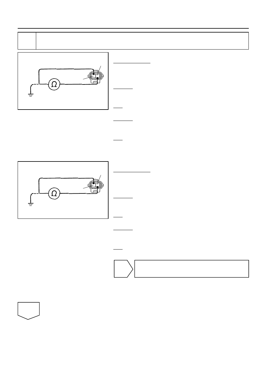
Check speed sensor.
Front:
PREPARATION:
(a)
Make sure that there is no looseness at the connector
lock part and connecting part of the connector.
(b)
Disconnect the speed sensor connector.
CHECK:
Measure the resistance between terminals 1 and 2 of the speed
sensor connector.
OK:
Resistance: 0.92
to 1.22
k
Ω
CHECK:
Measure the resistance between terminals 1 and 2 of the speed
sensor connector and body ground.
OK:
Resistance: 1 M
Ω
or higher
Rear:
PREPARATION:
(a)
Make sure that there is no looseness at the connector
lock part and connecting part of the connector.
(b)
Disconnect the speed sensor connector.
CHECK:
Measure the resistance between terminals 1 and 2 of the speed
sensor connector.
OK:
Resistance: 1.8 to 2.2 k
Ω
CHECK:
Measure the resistance between terminals 1 and 2 of the speed
sensor connector and body ground.
OK:
Resistance: 1 M
Ω
or higher
NG
Replace speed sensor
(See page
NOTICE:
Check the speed sensor signal after replacement (See
page
OK
BR3795
OK
NG
–
DIAGNOSTICS
ABS WITH EBD & BA & TRAC & VSC SYSTEM
DI–929
1123
3
Check for open and short circuit in harness and connector between each speed
sensor and skid control ECU (See page
NG
Repair or replace harness or connector.
OK
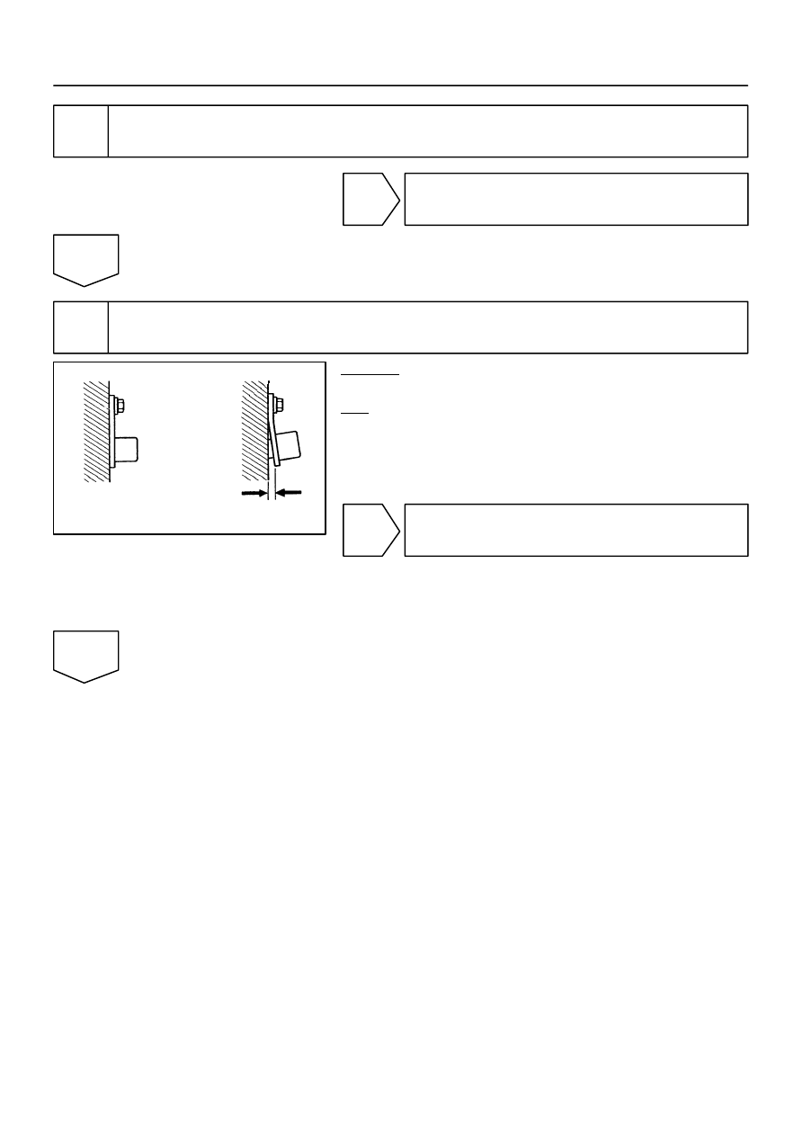
4
Check sensor installation.
CHECK:
Check the speed sensor installation.
OK:
The installation bolt is tightened properly and there is
no clearance between the sensor and the front steer-
ing knuckle or the rear axle carrier.
Torque: 8.0 N·m (82 kgf·cm, 71 in.·lbf)
NG
Replace speed sensor
(See page
NOTICE:
Check the speed sensor signal after replacement (See
page
OK
W04200
Normal Signal Waveform
1 V / Division
2 m/s / Division
GND
R07880
DI–930
–
DIAGNOSTICS
ABS WITH EBD & BA & TRAC & VSC SYSTEM
1124
5
Check speed sensor and sensor rotor serrations.
INSPECTION USING OSCILLOSCOPE
PREPARATION:
Connect the oscilloscope to the terminal FR+ – FR–, FL+ – FL–,
RR+ – RR– and RL+ – RL– of the skid control ECU.
CHECK:
Drive the vehicle at about 12 mph (20 km/h), and check the sig-
nal waveform.
OK:
A waveform as shown in the figure should be output.
HINT:
As the vehicle speed (wheel revolution speed) increases,
a cycle of the waveform becomes shorter and the fluctua-
tion in the output voltage becomes greater.
When noise is identified in the waveform on the oscillo-
scope, error signals are generated due to the speed sen-
sor rotor’s scratches, looseness or foreign matter depos-
ited on it.
OK
Replace skid control ECU
(See page
NOTICE:
When replacing the skid control ECU, perform the zero
point calibration (See page
NG
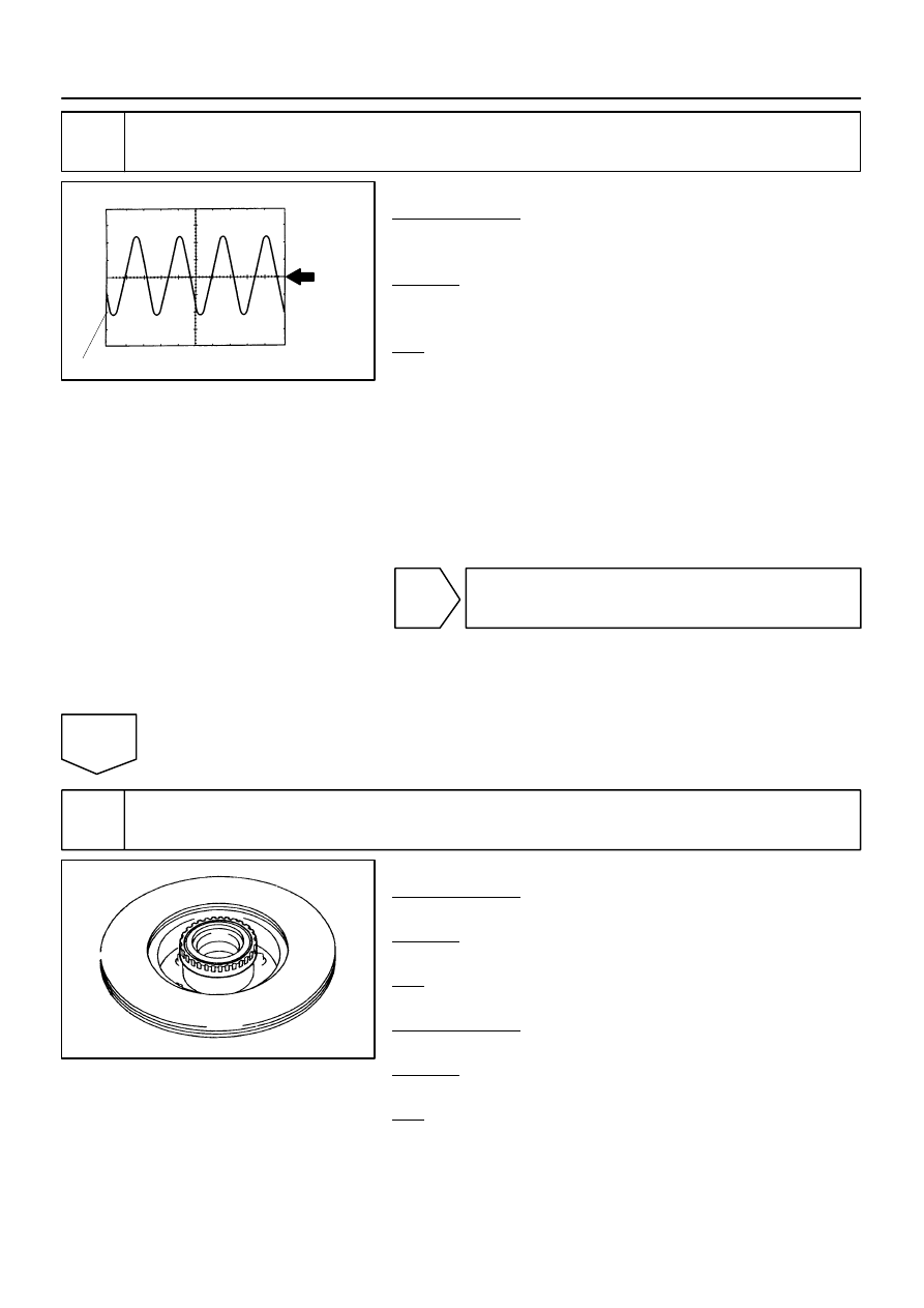
6
Check sensor rotor and sensor tip.
Front:
PREPARATION:
Remove the disc (See page
CHECK:
Check the sensor rotor serrations.
OK:
No scratches, missing teeth or foreign objects.
PREPARATION:
Remove the front speed sensor (See page
).
CHECK:
Check the sensor tip.
OK:
No scratches or foreign objects on the sensor tip.
HINT:
Remove any foreign matter if identified.
Check the output waveform again after reassembly.
Нет комментариевНе стесняйтесь поделиться с нами вашим ценным мнением.
Текст