Toyota Sequoia (2005). Manual — part 616
I28324
ACC
E
B+
B2+
GND
S10
S9
–
DIAGNOSTICS
NAVIGATION SYSTEM
DI–2259
2453
INSPECTION PROCEDURE
1
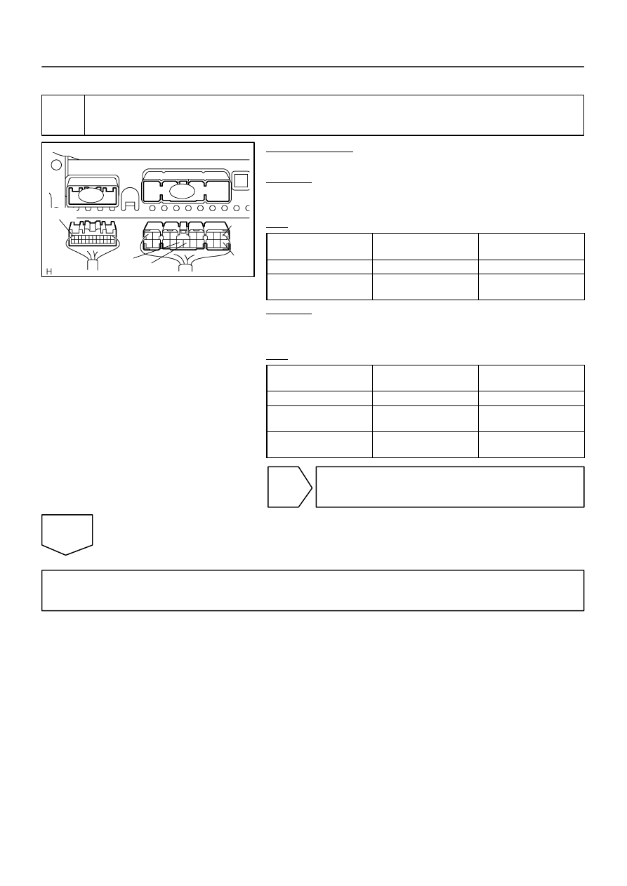
Inspect stereo component amplifier assy (B+, B2+, ACC, GND, E).
PREPARATION:
Disconnect the stereo component amplifier assy connectors.
CHECK:
Measure the resistance according to the value(s) in the table
below.
OK:
Symbol
(Tester connection)
Condition
Specified condition
E (S9–16) – Body ground
Always
Below 1
Ω
GND (S9–15) –
Body ground
Always
Below 1
Ω
CHECK:
Measure the voltage according to the value(s) in the table be-
low.
OK:
Symbol
(Tester connection)
Condition
Specified condition
B+ (S9–1) – GND (S9–15)
Always
10 to 14 V
B2+ (S9–10) –
GND (S9–15)
Always
10 to 14 V
ACC (S10–12) –
GND (S9–15)
Ignition SW ACC
10 to 14 V
NG
Repair or replace harness or connector.
OK
Proceed to next circuit inspection shown in problem symptoms table or diagnostic trouble code
chart (See page
I28766
R6
Light Control
Rheostat Assy
Radio and Navigation Assy
J/C
Steering Pad Switch Assy
Spiral Cable
Sub–assy
From
TAILLIGHT
Relay
ILL–
SWG
J/C
ILL+
W–G
G
J39
J40
J39
J40
J39
J40
W–G
G
G
G
A
B
A
A
A
B
ILL–
T
12
2
6
1
10
C9–1
BR–W
C9–10
6
4
Steering SW
R30
R27
R30
DI–2260
–
DIAGNOSTICS
NAVIGATION SYSTEM
2454
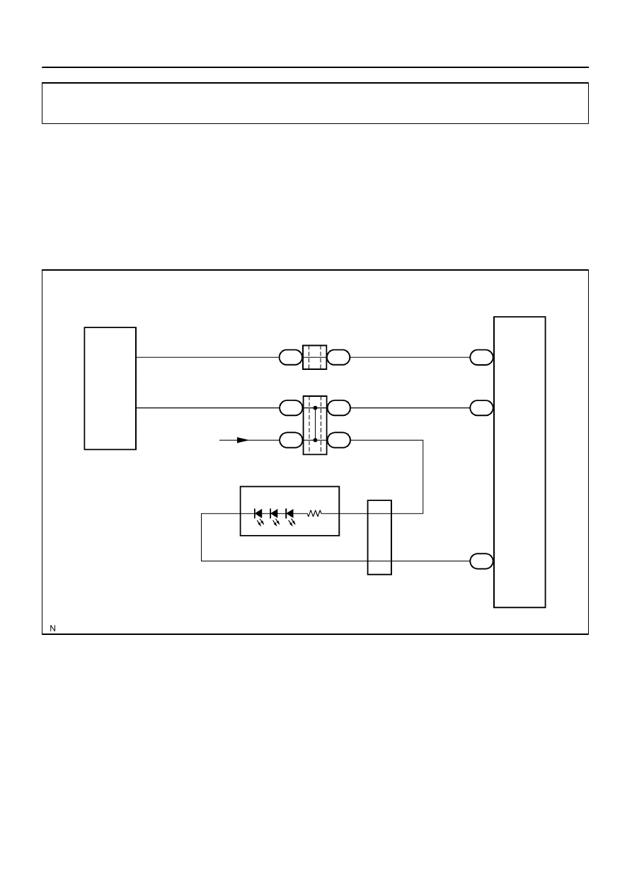
Illumination circuit
CIRCUIT DESCRIPTION
Power is supplied to the radio and navigation panel illumination when the light control switch is in the TAIL
or HEAD position. The body ECU determines the external brightness based on the brightness level detected
by the automatic light control sensor, and then operates the TAILLIGHT relay. Power can also be supplied
by operating the relay.
The intensity of the radio receiver panel illumination can be adjusted by the rheostat switch.
WIRING DIAGRAM
DIDDF–01
–
DIAGNOSTICS
NAVIGATION SYSTEM
DI–2261
2455
INSPECTION PROCEDURE
NOTICE:
The vehicle is equipped with SRS (Supplemental Restraint System) such as airbags. Before servic-
ing (including removal or installation of parts), be sure to read the precautionary notice for the sup-
plemental restraint system (See page
).
1
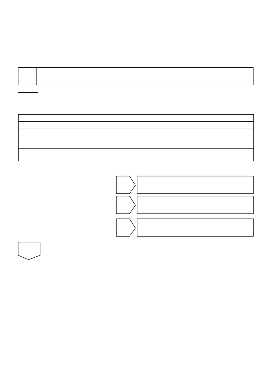
Check illumination.
CHECK:
Check if the illumination for the radio and navigation assy, steering pad switch assy or others (A/C switch,
cigarette lighter, etc.) comes on when the light control switch is turned to the HEAD or TAIL position.
RESULT:
Components with illumination
Go to step
Illumination comes on for all components except radio and navigation assy.
A
Illumination comes on for all components except steering pad switch.
B
Illumination comes on for all components except radio and navigation assy,
steering pad switch, Rear heater control panel, each switch, etc.
C
All illumination does not come on. (Radio and navigation assy, steering pad
switch, Combination meter, Rear heater control panel, each switch, etc.)
D
HINT:
If the illuminations have malfunctions, check the rheostat switch.
B
Go to step 4.
C
Go to step 8.
D
Go to combination meter system
(See page
A
I28747
R30
ILL+
DI–2262
–
DIAGNOSTICS
NAVIGATION SYSTEM
2456
2
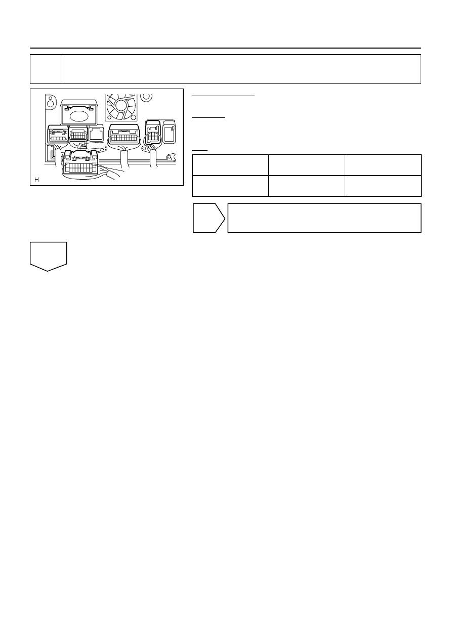
Check radio and navigation assy (ILL+).
PREPARATION:
Disconnect the radio and navigation assy connector.
CHECK:
Measure the voltage according to the value(s) in the table be-
low.
OK:
Symbol
(Tester connection)
Condition
Specified condition
ILL+ (R30–2) –
Body ground
Light control switch TAIL
10 to 14 V
NG
Repair or replace wire harness or connector
(Radio and navigation assy – battery).
OK
Нет комментариевНе стесняйтесь поделиться с нами вашим ценным мнением.
Текст