Toyota Sequoia (2005). Manual — part 617
I28747
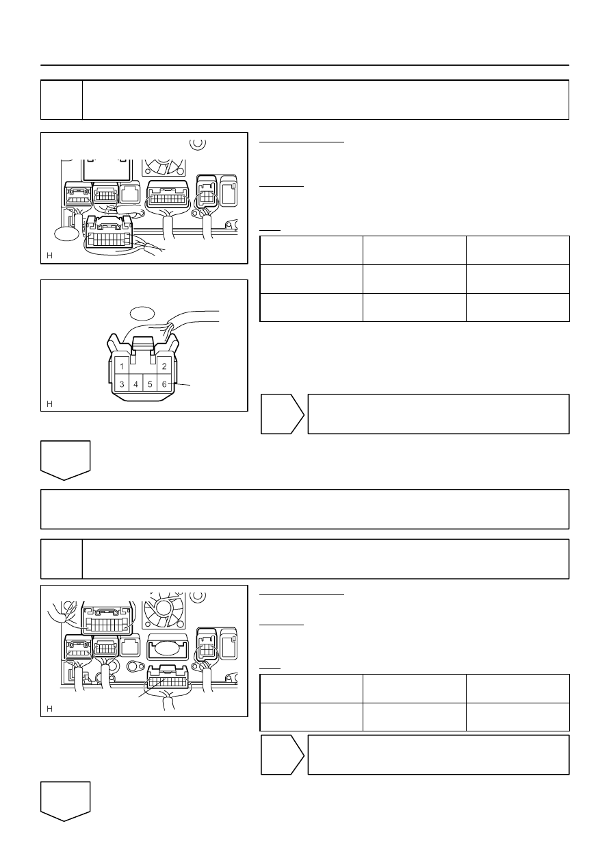
Radio and Navigation Assy
Wire Harness View:
R30
ILL–
I28577
R6
Light Control Rheostat
Wire Harness View:
ILL–
I28750
R27
SWG
Wire Harness View:
–
DIAGNOSTICS
NAVIGATION SYSTEM
DI–2263
2457
3
Check harness and connector (Radio and navigation assy – light control rheo-
stat).
PREPARATION:
Disconnect the radio and navigation assy and light control rheo-
stat connectors.
CHECK:
Measure the resistance according to the value(s) in the table
below.
OK:
Symbol
(Tester connection)
Condition
Specified condition
ILL– (R30–12) –
ILL– (R6–6)
Always
Below 1
Ω
ILL– (R30–12) –
Body ground
Always
10 k
Ω
or higher
NG
Repair or replace wire harness or connector.
OK
Replace radio and navigation assy.
4
Check radio and navigation assy.
PREPARATION:
Disconnect the radio and navigation assy connector.
CHECK:
Measure the voltage according to the value(s) in the table be-
low.
OK:
Symptom
(Tester connection)
Condition
Specified condition
SWG (R27–6) –
Body ground
Light control switch TAIL
10 to 14 V
OK
Replace radio and navigation assy.
NG
I28296
1
10
DI–2264
–
DIAGNOSTICS
NAVIGATION SYSTEM
2458
5
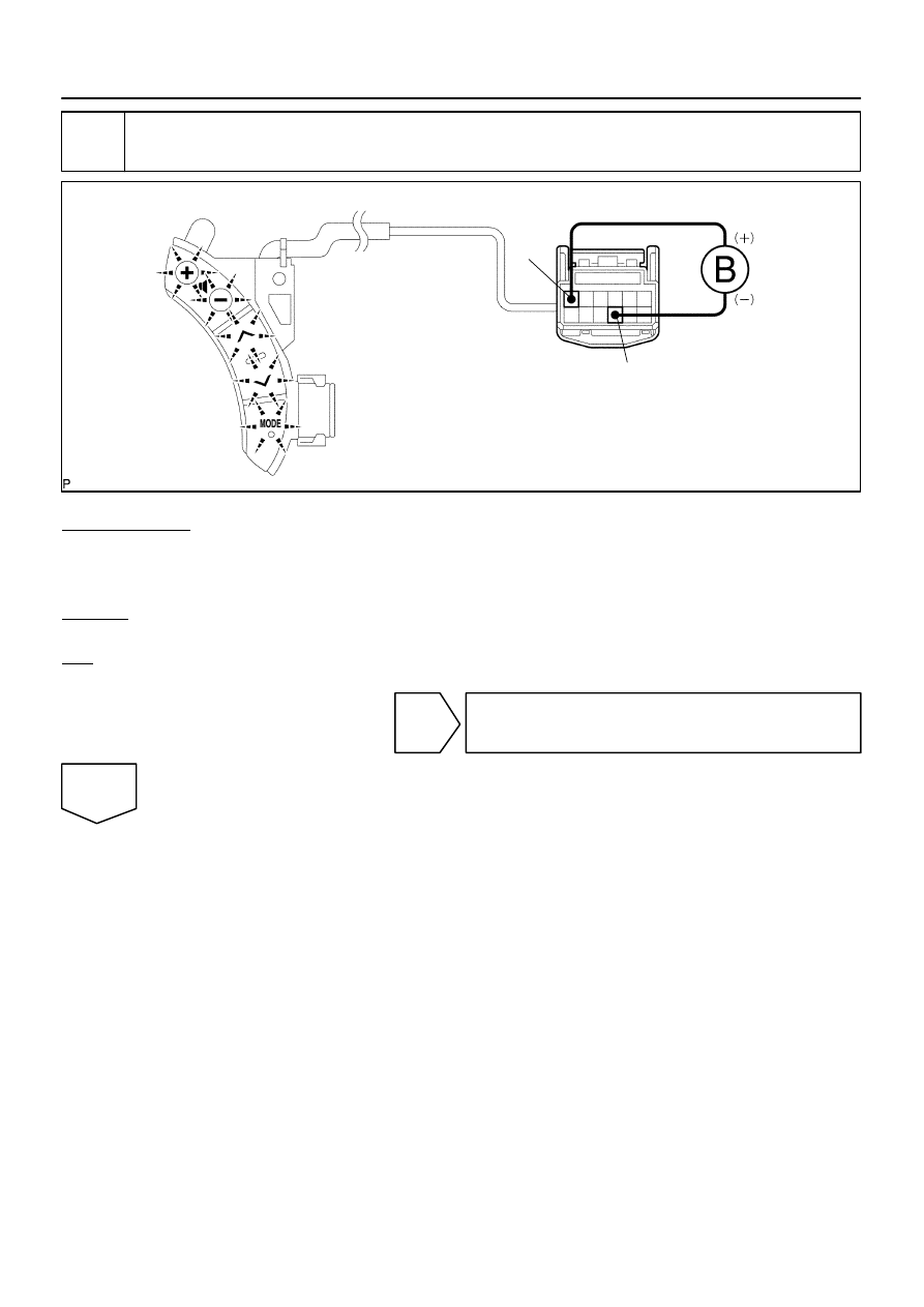
Inspect steering pad switch assy.
PREPARATION:
(a)
Disconnect the steering pad switch connector.
(b)
Connect the positive (+) lead to terminal 1 and the negative (–) lead to terminal 10 of steering pad
switch assy connector.
CHECK:
Check if the illumination for the steering pad switch assy comes on.
OK:
Illumination for the steering pad switch assy comes on.
NG
Replace steering pad switch assy.
OK
I28295
Vehicle Side:
Steering Pad Switch Assy Side:
C9
–
DIAGNOSTICS
NAVIGATION SYSTEM
DI–2265
2459
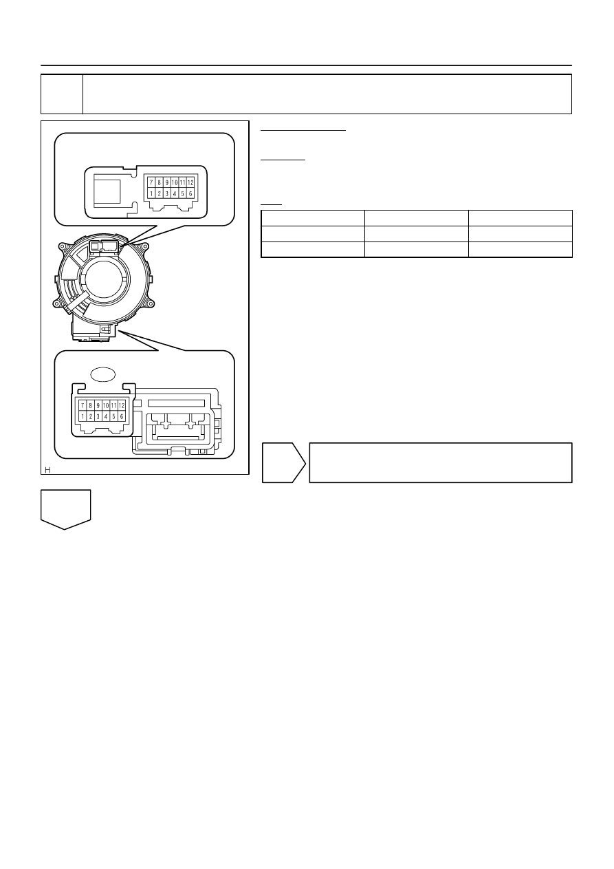
6
Inspect spiral cable sub–assy.
PREPARATION:
Remove the spiral cable sub–assy.
CHECK:
Measure the resistance according to the value(s) in the table
below.
OK:
Tester connection
Condition
Specified condition
C9–1 – 1
Always
Below 1
Ω
C9–10 – 10
Always
Below 1
Ω
NG
Replace spiral cable sub–assy.
OK
I28750
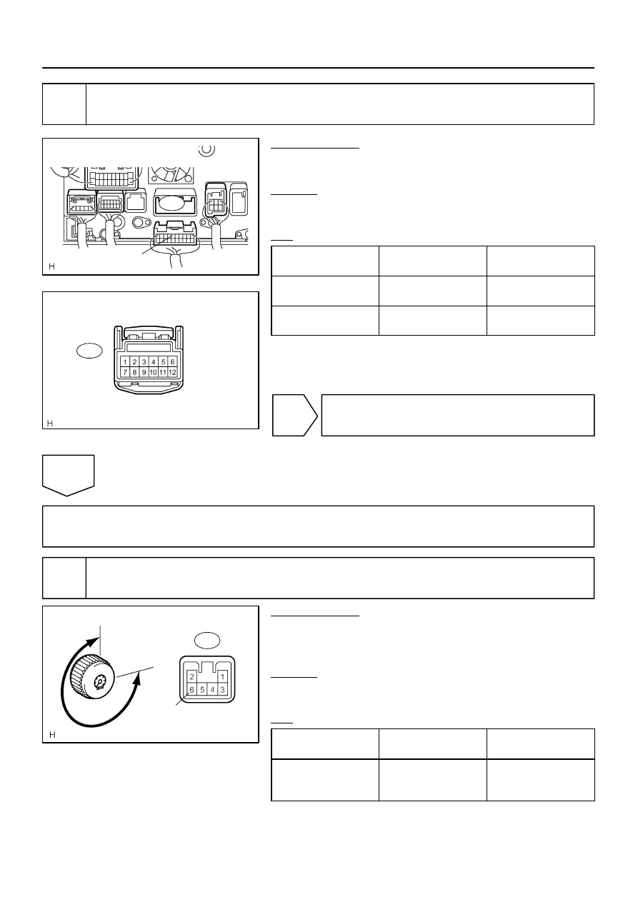
Radio and Navigation Assy
Wire Harness View:
R27
SWG
I28294
Spiral Cable Sub–assy
Connector Front View:
C9
I28576
270
°
Bright
0
°
Dark
R6
ILL–
DI–2266
–
DIAGNOSTICS
NAVIGATION SYSTEM
2460
7
Check harness and connector (Radio and navigation assy – spiral cable sub–
assy).
PREPARATION:
Disconnect the spiral cable sub–assy and radio and navigation
assy connectors.
CHECK:
Measure the resistance according to the value(s) in the table
below.
OK:
Symbol
(Tester connection)
Condition
Specified condition
SWG (R27–6) –
Spiral cable terminal 10
Always
Below 1
Ω
SWG (R27–6) –
Body ground
Always
10 k
Ω
or higher
NG
Repair or replace wire harness or connector
(Radio and navigation assy – spiral cable sub–
assy).
OK
Repair or replace wire harness or connector (Battery – spiral cable sub–assy).
8
Inspect light control rheostat.
PREPARATION:
(a)
Reconnect the light control rheostat switch connector.
(b)
Ignition switch is ON.
(c)
Light control switch is TAIL or HEAD.
CHECK:
Measure the voltage according to the value(s) in the table be-
low.
OK:
Symbol
(Tester connection)
Condition
Specified condition
ILL– (R6–6) –
Body ground
Rheostat knob to fully
counterclockwise
→
fully clockwise
Below 1 V
→
10 to 14 V
Нет комментариевНе стесняйтесь поделиться с нами вашим ценным мнением.
Текст