Toyota Sequoia (2005). Manual — part 615
I28261
–
DIAGNOSTICS
NAVIGATION SYSTEM
DI–2255
2449
Speed signal error
INSPECTION PROCEDURE
1
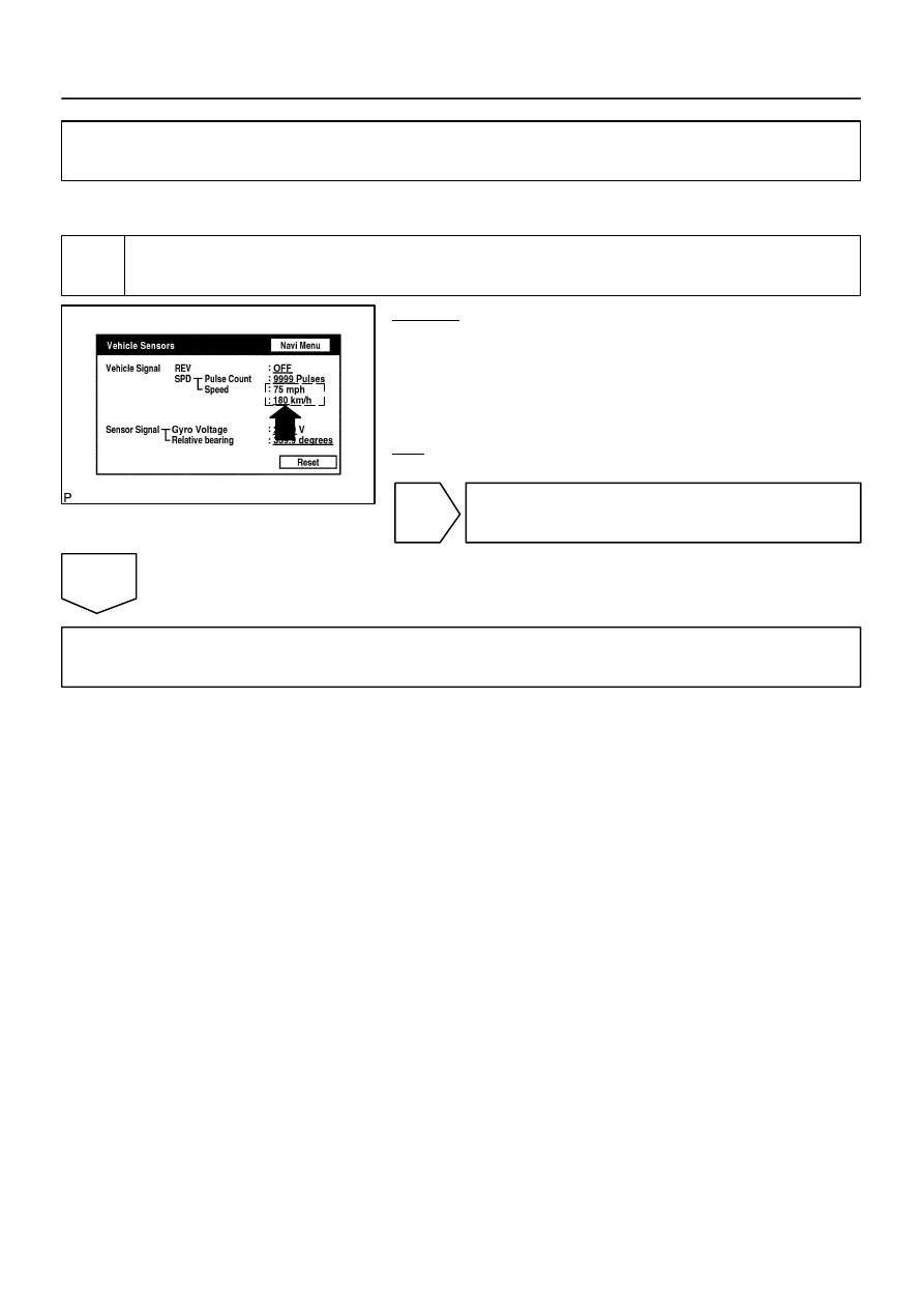
Navigation check mode (Vehicle sensors check).
CHECK:
(a)
Enter the ”Navigation Check” mode (Vehicle Sensors)
(See page
(b)
While driving, compare the ”SPD” indicator to the reading
on the speedometer. Check if these readings are almost
the same.
OK:
The readings are almost the same.
OK
Replace radio and navigation assy.
NG
Proceed to next circuit inspection shown in diagnostic trouble code chart (See page
DIDD9–01
I28474
11
Radio and
Navigation Assy
ACC
1
20
GND
GR
1
RAD No. 2
4
3
A36
ACC Cut Relay
P
3
1
AM1
ACC
12
Sub J/B No. 3
3A
W–R
W–R
1
IA1
24
L–Y
L–Y
2B
3
2C
8
2D
1
Engine Room J/B
RAD No. 1
ECU–B
Short Pin
1J
3
1E
W–R
1L
1
1C
6
AM1
2
ALT
B
Battery
IO
BR
R30
3A
I18
Ignition SW
W–L
B
2
12
1
1C
1F
GR
GR
B
C
B–O
J37
To ECM
J38
Instrument Panel J/B
1
2
B
R30
R30
J/C
P
W
W–R
B
8
5
4
F10
FL Block
DI–2256
–
DIAGNOSTICS
NAVIGATION SYSTEM
2450
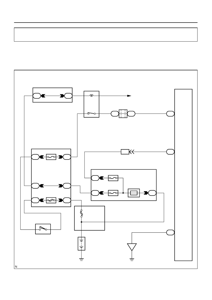
Power source circuit (Radio and navigation assy)
CIRCUIT DESCRIPTION
This circuit provides power to the radio and navigation assy.
WIRING DIAGRAM
DIDDB–01
I28292
B
GND
ACC
R30
–
DIAGNOSTICS
NAVIGATION SYSTEM
DI–2257
2451
INSPECTION PROCEDURE
1
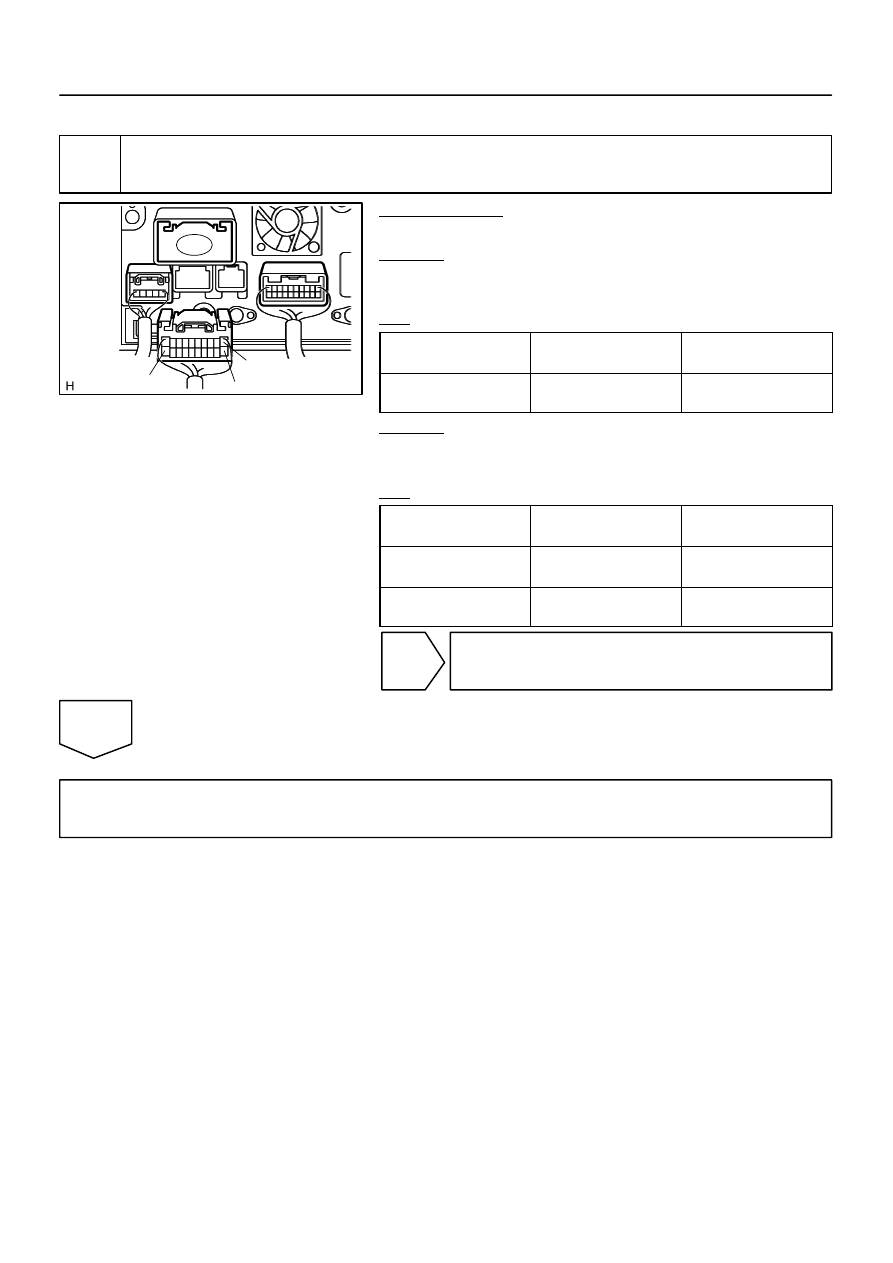
Inspect radio and navigation assy (B, ACC, GND).
PREPARATION:
Disconnect the radio and navigation assy connector.
CHECK:
Measure the resistance according to the value(s) in the table
below.
OK:
Symbol
(Tester connection)
Condition
Specified condition
GND (R30–20) –
Body ground
Always
Below 1
Ω
CHECK:
Measure the voltage according to the value(s) in the table be-
low.
OK:
Symbol
(Tester connection)
Condition
Specified condition
B (R30–1) –
GND (R30–20)
Always
10 to 14 V
ACC (R30–11) –
GND (R30–20)
Ignition switch is in ACC
10 to 14 V
NG
Repair or replace harness or connector.
OK
Proceed to next circuit inspection shown in problem symptoms table or diagnostic trouble code
chart (See page
I28475
GR
1
4
3
A36
ACC Cut Relay
12
Sub J/B No. 3
3A
W–R
1
2
3A
GR
B
C
B–O
J37
To ECM
J38
RAD No. 2
3
1
6
AM1
2
12
1
Instrument Panel J/B
1
2
P
3
AM1
ACC
W–R
W–L
ALT
B
Battery
W–R
IL1
2
L–W
2A
2C
8
2D
1
Engine Room J/B
RAD No. 3
ECU–B Short Pin
3
B
B
B
B
J11
J10
J11
L–W
IO
BR
BR
S10
S9
S9
S9
S9
12
10
15
16
1
ACC
B2+
B+
GND
E
Stereo Component
Amplifier Assy
1J
1E
1L
1C
1C
1F
J/C
J/C
B
1
GR
L–W
L–W
W–R
I18
Ignition SW
P
W
8
4
5
F10
FL Block
DI–2258
–
DIAGNOSTICS
NAVIGATION SYSTEM
2452
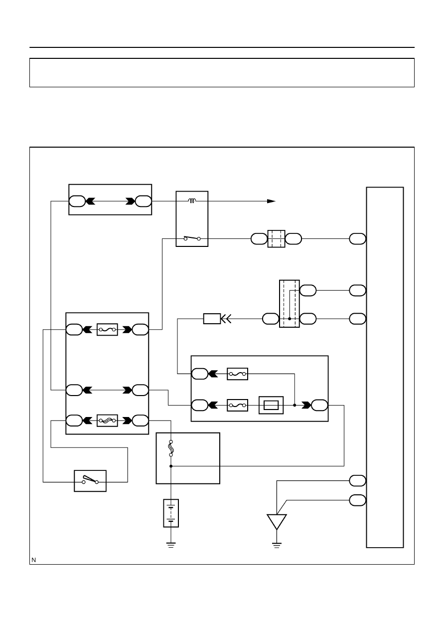
Power source circuit (Stereo component amplifier assy)
CIRCUIT DESCRIPTION
This circuit provides power to the stereo component amplifier assy.
WIRING DIAGRAM
DIDDD–01
Нет комментариевНе стесняйтесь поделиться с нами вашим ценным мнением.
Текст