Toyota Sequoia (2005). Manual — part 695
SF0P0–14
BO0919
Crack
Leakage
Deformation
FU0041
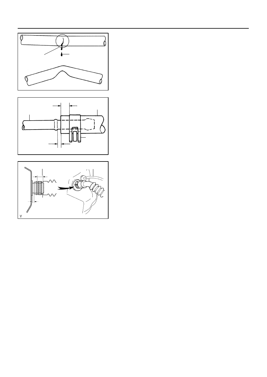
Pipe
Clip
2 to 7 mm (0.08 to 0.28 in.)
0 to 3 mm (0 to 0.12 in.)
Hose
B17498
Fuel Inlet Hose
Clamp
0 to 3 mm
(0 to 0.12 in.)
Hose Clamp Area
–
SFI
FUEL TANK AND LINE
SF–35
2769
INSPECTION
INSPECT FUEL TANK AND LINE
(a)
Check the fuel lines for cracks or leakage, and all connec-
tions for deformation.
(b)
Check the fuel tank vapor vent system hoses and connec-
tions for looseness, sharp bends or damage.
(c)
Check the fuel tank for deformation, cracks, fuel leakage
or tank band looseness.
(d)
Check the filler neck for damage or fuel leakage.
(e)
Hose and pipe connections are as shown in the illustra-
tion.
If a problem is found, repair or replace the parts as necessary.
SF1XI–01
B17583
B17582
B17581
SF–36
–
SFI
FUEL TANK AND LINE
2770
INSTALLATION
1.
INSTALL FUEL PUMP ASSEMBLY (See page
2.
INSTALL FUEL TANK ASSEMBLY
(a)
Set up the fuel tank to the transmission jack.
(b)
Operate the transmission jack and install the fuel tank.
(c)
Install the 2 fuel tank bands with the 2 bolts.
Torque: 62 N·m (632 kgf·cm, 45 ft·lbf)
3.
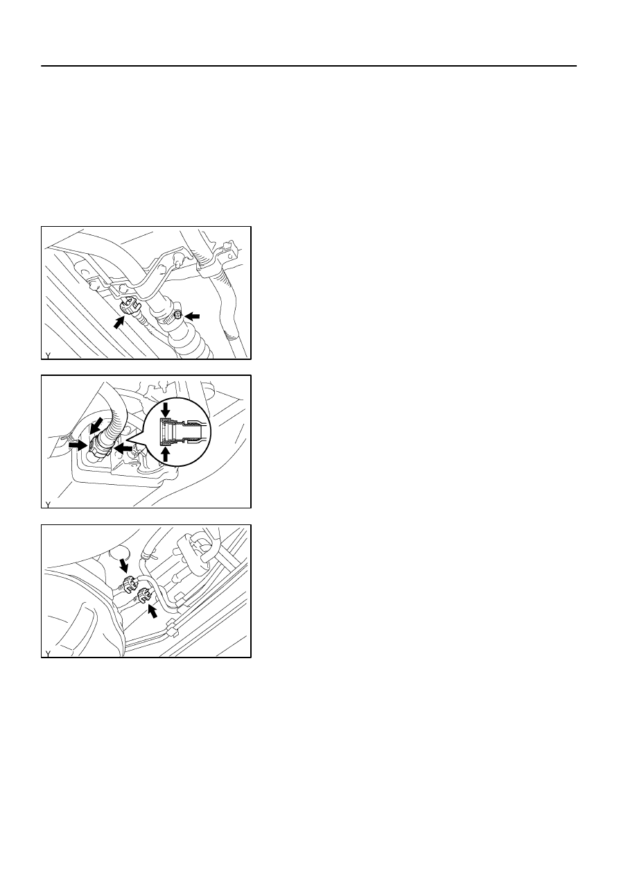
CONNECT FUEL INLET HOSE AND BREATHER TUBE
(a)
Connect the fuel inlet hose to the filler pipe and install the
clamp.
(b)
Connect the breather tube. (See page
)
4.
DISCONNECT FUEL TANK VENT HOSE
Connect the fuel tank vent hose to the charcoal canister.
5.
CONNECT FUEL MAIN TUBE AND RETURN TUBE
(See page
)
6.
INSTALL FUEL TANK PROTECTOR
Install the fuel tank protector with the 2 bolts and 2 nuts.
7.
CONNECT FUEL PUMP CONNECTOR
8.
CHECK FOR FUEL LEAKS
9.
INSTALL SPARE TIRE
SF0P1–12
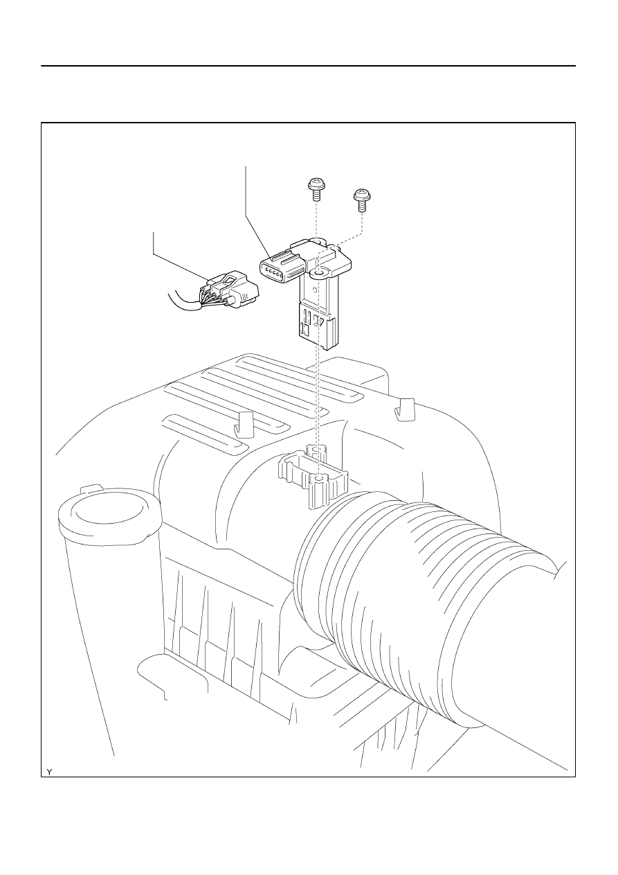
B17463
MAF Meter Connector
MAF Meter
–
SFI
MASS AIR FLOW (MAF) METER
SF–37
2771
MASS AIR FLOW (MAF) METER
COMPONENTS
B17464
3
2
1
4 5
–20
0
20
40
60
80
100
0.1
0.2
0.3
0.5
1
2
3
5
10
20
30
TEMPERATURE
C(
F)
RESIST
ANCE k
Ω
(–4) (32) (68)
(140)
(104)
(212)
(176)
Air
E2
THA
VG
E2G
+B
Acceptable
SF0P2–09
B17465
Air
B17466
ECM
VG
E2G
Voltmeter
SF–38
–
SFI
MASS AIR FLOW (MAF) METER
2772
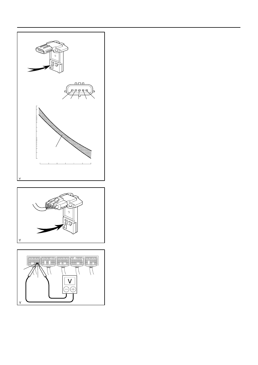
INSPECTION
1.
INSPECT OUTPUT VOLTAGE
(a)
Apply battery voltage across terminals 1 (+B) and 2
(E2G).
(b)
Connect the positive (+) tester probe to terminal 3 (VG),
and the negative (–) tester probe to terminal 2 (E2G).
(c)
Blow air into the MAF meter, and check if the voltage fluc-
tuates.
2.
INSPECT RESISTANCE
Using an ohmmeter, measure the resistance between terminals
4 (THA) and 5 (E2).
Resistance:
12.5 to 16.9 k
Ω
at –20
C (–4
F)
2.19 to 2.67 k
Ω
at 20
C (68
F)
0.50 to 0.68 k
Ω
at 60
C (140
F)
3.
INSPECT MASS AIR FLOW METER
(a)
If using a hand–held tester:
(1)
Connect the hand–held tester to the DLC3.
(2)
Turn the ignition switch to the ON position.
(3)
Blow air into the MAF meter, and check that the air
flow value of the CURRENT DATA changes.
If operation is not as specified, check the MAF meter (see page
and
) as well as the wiring and the ECM.
(b)
If not using a hand–held tester:
(1)
Turn the ignition switch to the ON position.
(2)
Connect the positive tester probe of the voltmeter
to terminal VG of the ECM and the negative tester
probe of the voltmeter to terminal E2G of the ECM.
(3)
Blow air into the air flow meter, and check if the volt-
age fluctuates.
If operation is not as specified, check the MAF meter (see page
and
), the wiring and the ECM.
Нет комментариевНе стесняйтесь поделиться с нами вашим ценным мнением.
Текст