Toyota Sequoia (2005). Manual — part 693
SF133–08
B07312
B16540
(a)
(b)
Throttle Body Cover Bracket
(c)
B07045
Clamp
Clamp
Clamp
–
SFI
INJECTOR
SF–27
2761
REMOVAL
1.
DISCHARGE FUEL SYSTEM PRESSURE
(See page
)
2.
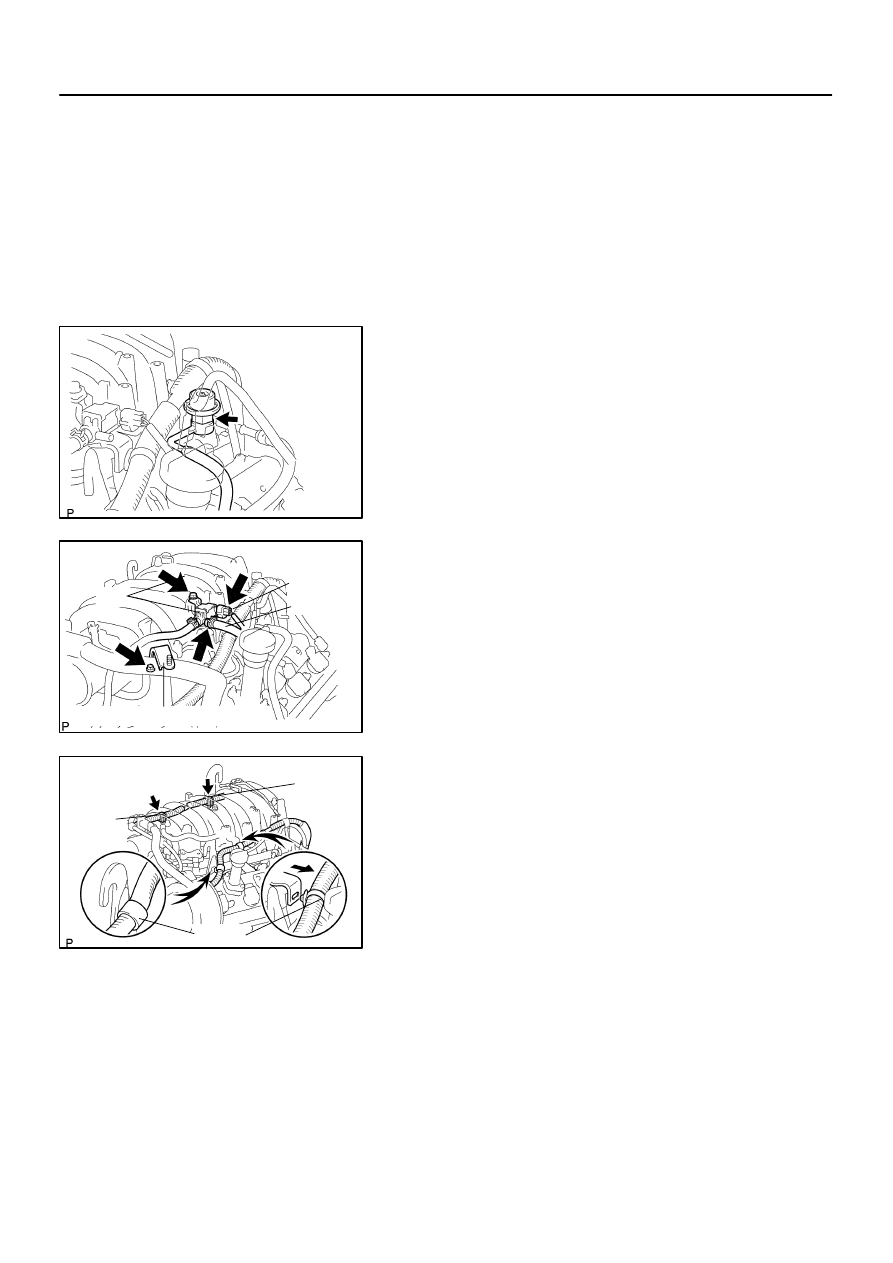
REMOVE THROTTLE BODY COVER
3.
REMOVE INTAKE AIR CONNECTOR
4.
REMOVE FUEL PRESSURE PULSATION DAMPER
Remove the pulsation damper, upper gasket, fuel main hose
and lower gasket.
NOTICE:
Put a shop rag under the delivery pipe.
Slowly loosen the pulsation damper.
5.
DISCONNECT PCV HOSE FROM PCV VALVE
6.
DISCONNECT VSV FOR EVAP
(a)
Disconnect the VSV connector for EVAP.
(b)
Disconnect the EVAP hose.
(c)
Remove the VSV for EVAP from the intake manifold.
7.
REMOVE THROTTLE BODY COVER BRACKET
Remove the bolt and throttle body cover bracket.
8.
DISCONNECT ENGINE WIRES
(a)
Disconnect the engine wire clamps from the No.1 engine
hanger and engine wire bracket.
(b)
Disconnect the 2 wire clamps on the engine wire from the
brackets on the RH delivery pipe.
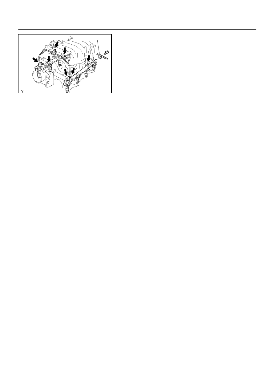
9.
REMOVE DELIVERY PIPES AND INJECTORS
NOTICE:
Be careful not to drop the injectors when removing
the delivery pipes.
Do not apply any load to the injector in horizontal
direction.
B17461
Fuel Return Pipe
SF–28
–
SFI
INJECTOR
2762
(a)
Remove the bolt holding the clamp on the fuel return pipe
to the LH delivery pipe.
(b)
Remove the bolt, 2 union bolts, 4 gaskets and front fuel
pipe.
(c)
Disconnect the 8 injector connectors.
(d)
Remove the 4 nuts holding the delivery pipes to the lower
intake manifold.
(e)
Remove the 2 delivery pipes, 8 injectors, and 8 insulators.
(f)
Remove the O–ring and grommet from each injector.
SF134–04
B07326
SST
Injector
SST
SST
SST
Pressure Regulator
B04988
Pressure Regulator
SST (Hose)
SST (Union)
Fuel Return Hose
B00884
SST
(Adaptor)
SST
(Hose)
SST
(Clamp)
Vinyl
Hose
O–Ring
D13872
Hand–Held Tester
DLC3
CAN VIM
–
SFI
INJECTOR
SF–29
2763
INSPECTION
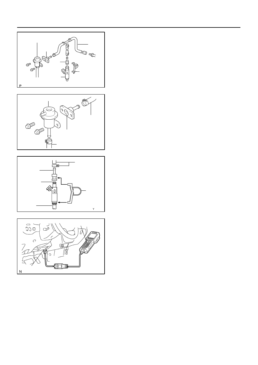
1.
INSPECT INJECTOR INJECTION
CAUTION:
Keep the injector clean of sparks during the test.
(a)
Disconnect the fuel inlet hose (fuel tube connector) from
the fuel filter.
(b)
Connect SST (attachment and hose) to the fuel tube.
SST
09268–41047 (09268–52011)
(c)
Remove the pressure regulator from the delivery pipe.
(d)
Install the O–ring to the fuel inlet of the pressure regulator.
(e)
Connect SST (hose) to the fuel inlet of the pressure regu-
lator with SST (union) and the 2 bolts.
SST
09268–41047 (09268–41091)
Torque: 7.5 N·m (76 kgf·cm, 66 in.·lbf)
(f)
Connect the fuel return hose to the fuel outlet of the pres-
sure regulator.
(g)
Install the O–ring to the injector.
(h)
Connect SST (adaptor and hose) to the injector, and hold
the injector and union with SST (clamp).
SST
09268–41047 (09268–41110, 09268–41300)
(i)
Put the injector into the graduated cylinder.
CAUTION:
Install a suitable vinyl hose onto the injector to prevent
gasoline from splashing out.
(j)
Connect a hand–held tester to the Controller Area Net-
work Vehicle Interface Module (CAN VIM). Then connect
the CAN VIM to the Date Link Connector 3 (DLC3).
(k)
Connect the battery negative (–) cable to the battery.
(l)
Turn the ignition switch ON, and push the hand–held tes-
ter main switch ON.
NOTICE:
Do not start the engine.
(m)
Enter the following menus: DIAGNOSIS / ENHANCED
OBDII / ACTIVE TEST / FUEL PUMP / SPD
(n)
Please refer to the hand–held tester operator’s manual
for further details.
B00883
Connect
SST
(Wire)
A01293
SF–30
–
SFI
INJECTOR
2764
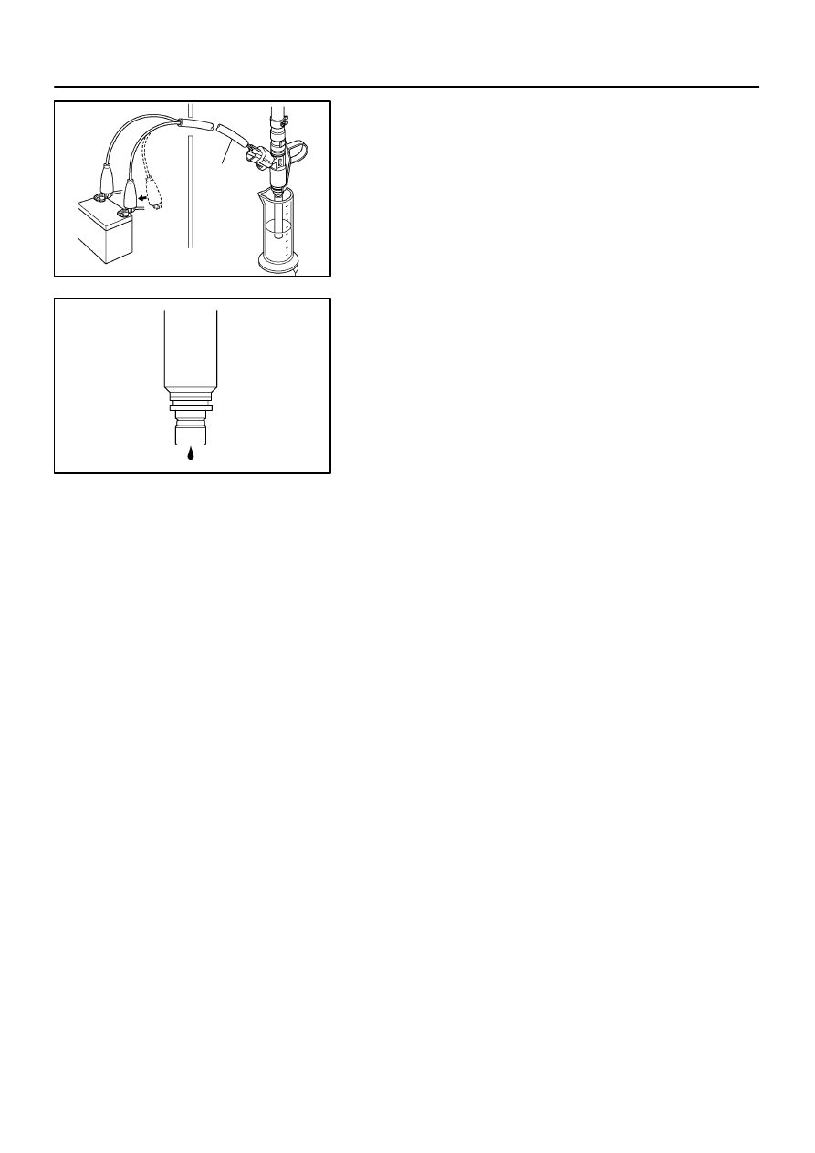
(o)
Connect SST (wire) to the injector and battery for 15 se-
conds, and measure the injection volume with a gra-
duated cylinder. Test each injector 2 or 3 times.
SST
09842–30070
Volume: 56 to 69 cm
3
(3.4 to 4.2 cu in.) per 15 seconds
Difference between each injector:
13 cm
3
(0.8 cu in.) or less
If the injection volume is not as specified, replace the injector.
2.
INSPECT LEAKAGE
(a)
Under the above conditions, disconnect the tester probes
of SST (wire) from the battery and check fuel leakage
from the injector.
SST
09842–30070
Fuel drop: 1 drop or less per 12 minutes
(b)
Turn the ignition switch off.
(c)
Disconnect the negative (–) terminal cable from the bat-
tery.
(d)
Remove the SST and fuel tube connector.
SST
09268–41047, 09842–30070
(e)
Disconnect the hand–held tester and CAN VIM from the
DLC3.
(f)
Reconnect the fuel inlet pipe to the fuel tube.
Нет комментариевНе стесняйтесь поделиться с нами вашим ценным мнением.
Текст