Toyota Sequoia (2005). Manual — part 694
SF135–06
A01296
New Grommet
New O–Ring
B04439
Outward
Turn
Push
Connector
B17461
Fuel Return Pipe
B04438
Rotate
Outward
Connector
–
SFI
INJECTOR
SF–31
2765
INSTALLATION
1.
INSTALL INJECTORS AND DELIVERY PIPES
NOTICE:
Be careful not to drop the injectors when installing
the delivery pipes.
Do not apply any load to the injector on horizontal
direction.
(a)
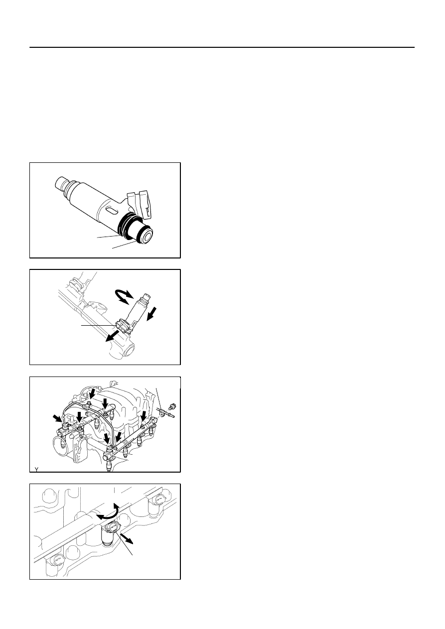
Install a new grommet to each injector.
(b)
Apply a light coat of gasoline to a new O–ring and install
it to each injector.
(c)
While turning the injector clockwise and counterclock-
wise, push it to the delivery pipes. Install the 8 injectors.
(d)
Position the injector connector outward.
(e)
Place the 8 new insulators on the intake manifold.
(f)
Place the 2 delivery pipes and injectors assemblies on the
lower intake manifold.
(g)
Temporarily install the 4 nuts.
(h)
Install the front fuel pipe with the bolt, 4 new gaskets and
2 union bolts.
Torque:
39 N·m (400 kgf·cm, 29 ft·lbf) for union bolts
7.5 N·m (76 kgf·cm, 66 in.·lbf) for bolt
(i)
Install the bolt holding the clamp on the fuel return pipe to
the LH delivery pipe.
Torque: 7.5 N·m (76 kgf·cm, 66 in.·lbf)
(j)
Check that the injectors rotate smoothly.
HINT:
If the injectors do not rotate smoothly, the probable cause is in-
correct installation of O–rings. Replace the O–ring of the injec-
tor that does not rotate smoothly.
(k)
Position injector connector outward.
(l)
Tighten the 4 nuts holding the delivery pipes to the lower
intake manifold.
Torque: 21 N·m (214 kgf·cm, 15 ft·lbf)
B07534
Clamp
Clamp
B16540
(a)
(c)
(b)
Throttle Body Cover Bracket
SF–32
–
SFI
INJECTOR
2766
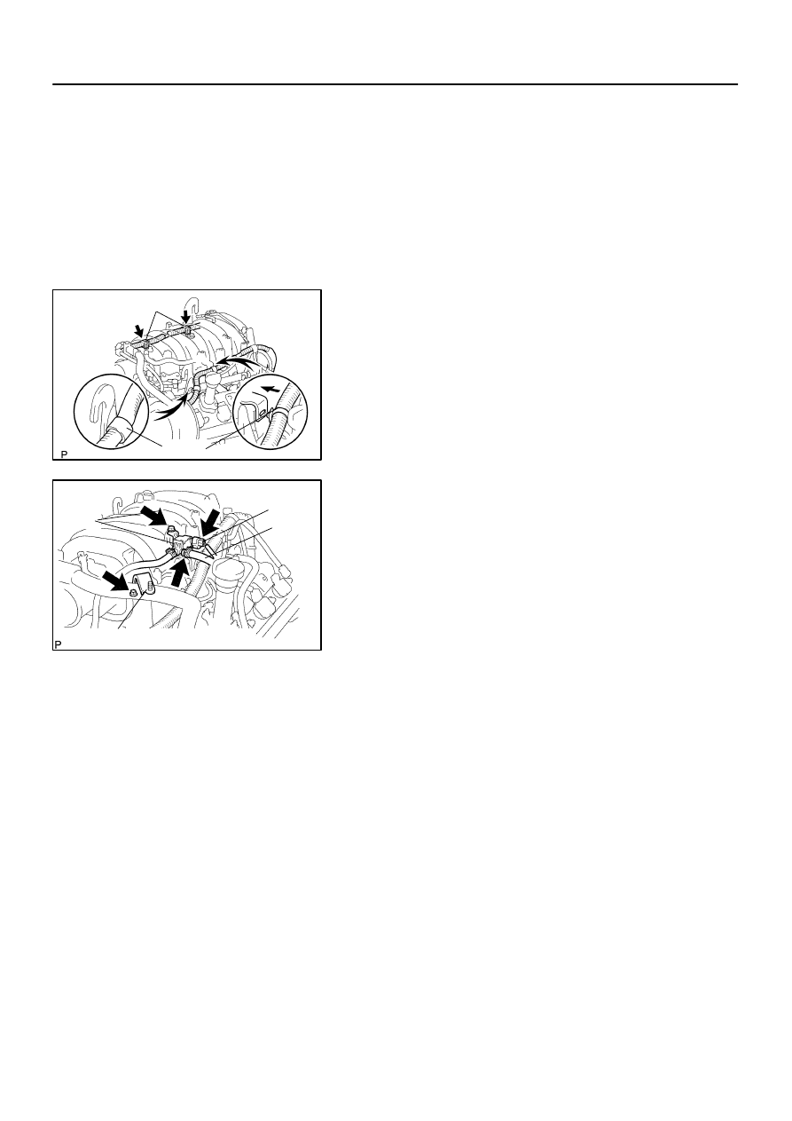
(m)
Connect the 8 injector connectors.
2.
INSTALL ENGINE WIRES
(a)
Install the 2 wire clamps on the engine wire to the brackets
on the RH delivery pipe.
(b)
Connect the engine wire clamps to the No.1 engine hang-
er and engine wire bracket.
(c)
Install the engine wire protector with the 2 bolts.
3.
CONNECT PCV HOSE TO PCV VALVE
4.
CONNECT VSV FOR EVAP TO UPPER INTAKE MAN-
IFOLD
(a)
Install the VSV for the EVAP to the upper intake manifold.
(b)
Connect the EVAP hose.
(c)
Connect the VSV connector for the EVAP.
5.
INSTALL THROTTLE BODY COVER BRACKET
Install the throttle body cover bracket with the bolt.
6.
INSTALL FUEL PRESSURE PULSATION DAMPER
(See page
)
7.
INSTALL INTAKE AIR CONNECTOR
8.
INSTALL THROTTLE BODY COVER
SF0OZ–17
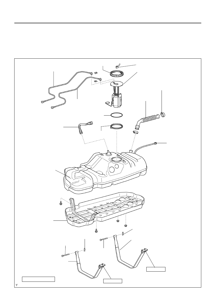
B17462
Fuel Inlet Pipe
Shield
No.1 Fuel Tank Band
N·m (kgf·cm, ft·lbf) : Specified torque
Non–reusable part
Gasket
Fuel Pump and
Sender Gauge
Assembly
Fuel Tank
Vent Hose
No.2 Fuel Tank Band
Fuel Inlet Pipe
Fuel Tank Band Pin
62 (632, 45)
Fuel Tank
Protector
Fuel Tank Band Pin
Fuel Return Tube
62 (632, 45)
Fuel Tank
Band Pin
Fuel Tank Band Pin
Recirculation
Tube
Fuel Main Tube
Fuel Pump Connector
Fuel Pump Gauge
Retainer
Fuel Pump Suction
Support
–
SFI
FUEL TANK AND LINE
SF–33
2767
FUEL TANK AND LINE
COMPONENTS
CAUTION:
Always use new gaskets when replacing the fuel tank or component parts.
Apply the proper torque to all parts tightened
SF1XH–01
B17581
B17582
B17583
SF–34
–
SFI
FUEL TANK AND LINE
2768
REMOVAL
1.
DISCHARGE FUEL SYSTEM PRESSURE
(See page
)
2.
REMOVE SPARE TIRE
3.
DISCONNECT FUEL PUMP CONNECTOR
4.
REMOVE FUEL TANK PROTECTOR
Remove the 2 bolts, 2 nuts and fuel tank protector.
5.
DISCONNECT FUEL MAIN TUBE AND RETURN TUBE
(See page
)
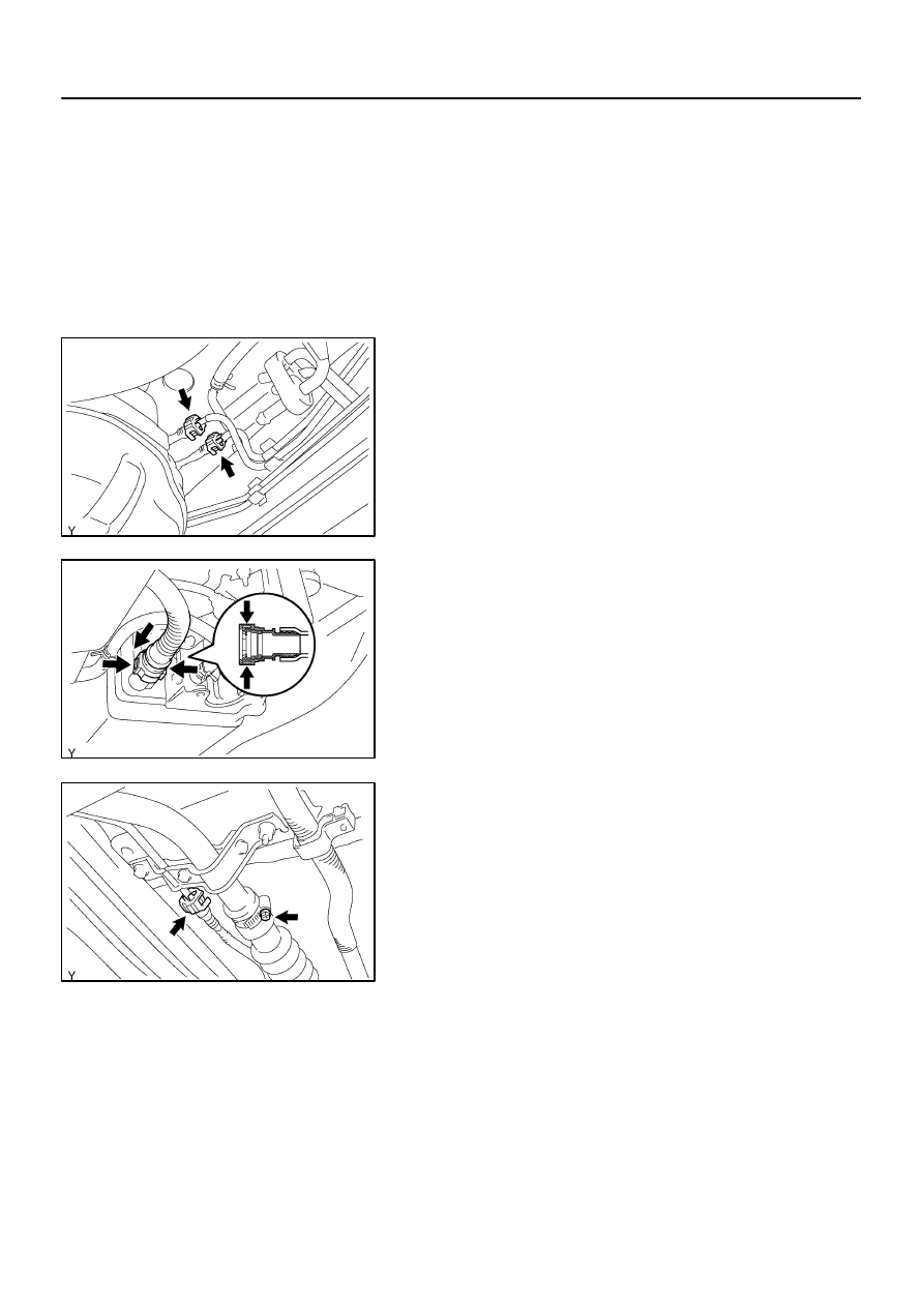
6.
DISCONNECT FUEL TANK VENT HOSE
(a)
Push the connector deep into the charcoal canister to re-
lease the locking tab.
(b)
Pinch portion A.
(c)
Pull out the connector.
7.
DISCONNECT INLET HOSE AND BREATHER HOSE
(a)
Loosen the hose clamp bolt and disconnect the fuel inlet
hose from the fuel filler pipe.
(b)
Disconnect the breather tube. (See page
8.
REMOVE FUEL TANK ASSEMBLY
(a)
Set up a transmission jack under the fuel tank.
(b)
Remove the 2 bolts and disconnect the 2 fuel tank bands
from the fuel tank.
(c)
Operate the transmission jack and remove the fuel tank.
9.
REMOVE FUEL PUMP ASSEMBLY
(See page
Нет комментариевНе стесняйтесь поделиться с нами вашим ценным мнением.
Текст