Toyota Sequoia (2005). Manual — part 549
I28498
11
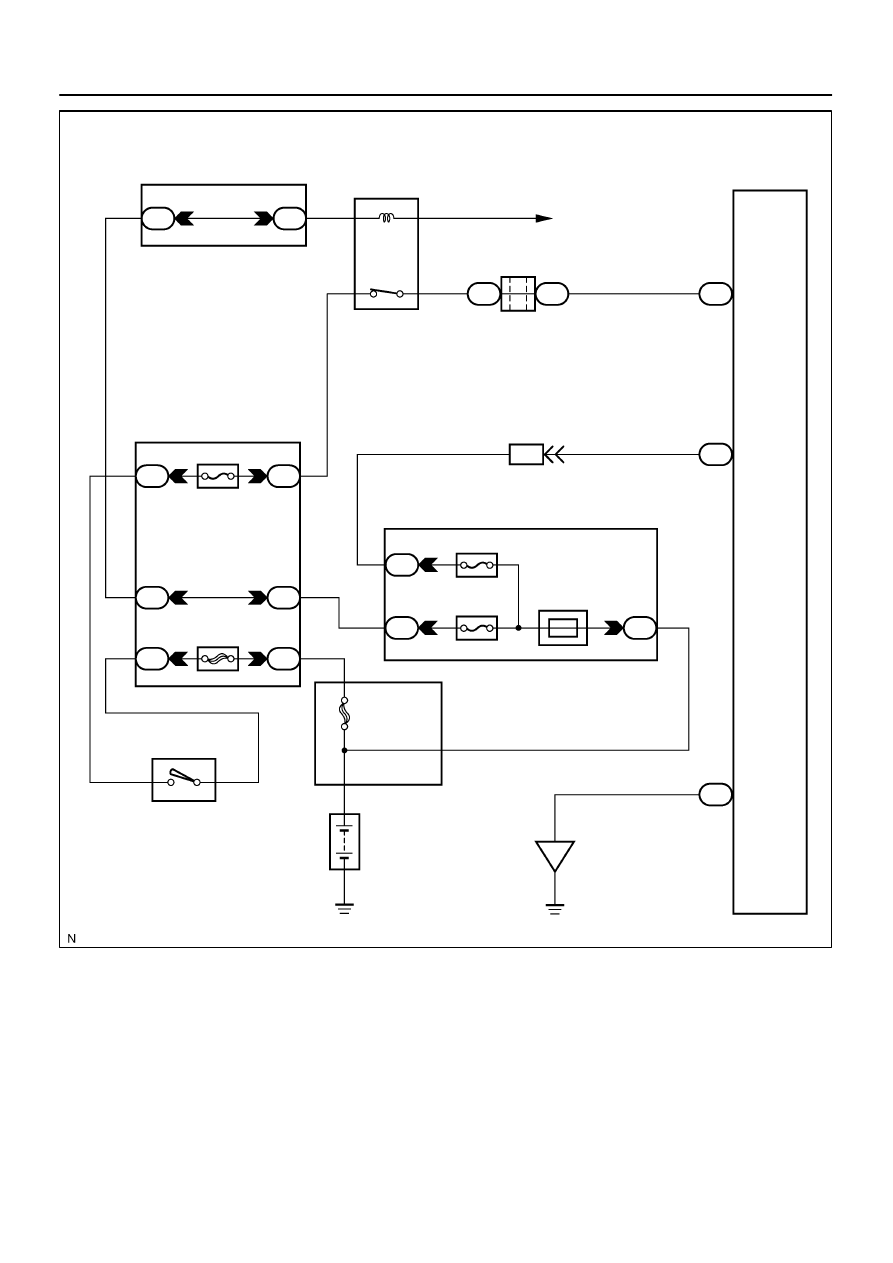
Radio Receiver Assy
ACC+B
1
R4
20
GND
GR
1
RAD No. 2
4
3
A36
ACC Cut Relay
P
3
1
AM1
ACC
12
Sub J/B No. 3
3A
W–R
W–R
1
IA1
24
L–Y
L–Y
2B
3
2C
8
2D
1
Engine Room J/B
RAD No. 1
ECU–B
Short Pin
1J
3
1E
W–R
1L
1
1C
6
AM1
2
ALT
5
B
Battery
IO
BR
Separate Type Amplifier:
R4
R4
3A
I18
Ignition SW
W–L
B
2
12
1
1C
1F
GR
GR
B
C
B–O
J37
To ECM
J38
Instrument Panel J/B
1
2
BU+B
W
8
4
F10
Fusible Link Block
J/C
–
DIAGNOSTICS
AUDIO SYSTEM
DI–1991
2185
I28739
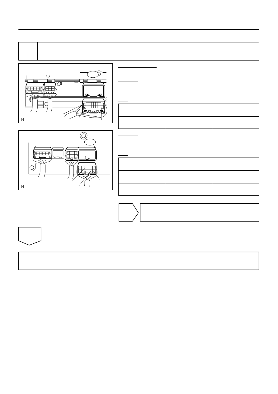
Separate Type Amplifier
Wire Harness View:
GND
ACC+B
BU+B
R4
I28743
Built–in Type Amplifier
Wire Harness View:
GND
ACC+B
BU+B
R2
DI–1992
–
DIAGNOSTICS
AUDIO SYSTEM
2186
INSPECTION PROCEDURE
1
Inspect radio receiver assy.
PREPARATION:
Disconnect the radio receiver assy connector.
CHECK:
Measure the resistance according to the value(s) in the table
below.
OK:
Symbol
(Tester connection)
Condition
Specified condition
GND (R2–7, R4–20) –
Body ground
Always
Below 1
Ω
CHECK:
Measure the voltage according to the value(s) in the table be-
low.
OK:
Symbol
(Tester connection)
Condition
Specified condition
BU+B (R2–4, R4–1) –
GND (R2–7, R4–20)
Always
10 to 14 V
ACC+B (R2–3, R4–11) –
GND (R2–7, R4–11)
Ignition SW ACC
10 to 14 V
NG
Repair or replace harness or connector
(Radio receiver assy – battery or body ground).
OK
Proceed to next circuit inspection shown in problem symptoms table or diagnostic trouble code
chart (See page
I28500
GR
1
4
3
A36
ACC Cut Relay
12
Sub J/B No. 3
3A
W–R
1
2
3A
GR
B
C
B–O
J37
To ECM
J38
RAD No. 2
3
1
6
AM1
2
12
1
Instrument Panel J/B
1
2
P
3
AM1
ACC
W–R
W–L
ALT
5
B
Battery
W–R
ILI
2
L–W
2A
2C
8
2D
1
Engine Room J/B
RAD No. 3
ECU–B
Short Pin
3
B
B
B
B
J11
J10
J11
L–W
IO
BR
BR
S10
S9
S9
S9
S9
12
10
15
16
1
ACC
B2+
B+
GND
E
Stereo Component
Amplifier Assy
1J
1E
1L
1C
1C
1F
J/C
J/C
GR
8
4
F10
Fusible Link Block
W
L–W
L–W
I18
Ignition SW
–
DIAGNOSTICS
AUDIO SYSTEM
DI–1993
2187
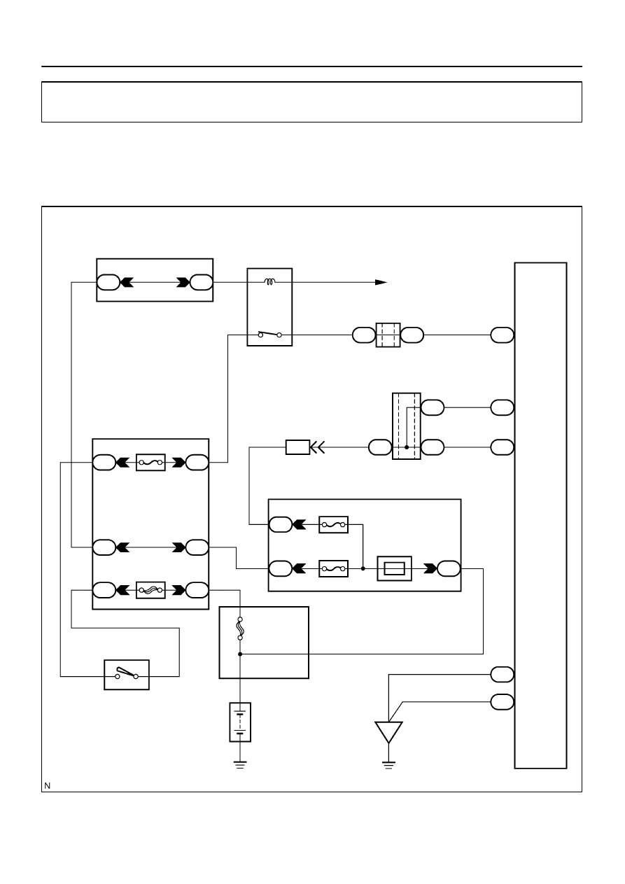
Power source circuit (Stereo component amplifier assy)
CIRCUIT DESCRIPTION
This circuit provides power to the stereo component amplifier assy.
WIRING DIAGRAM
DID9V–01
I28324
GND
ACC
B2+
E
B+
S9
S10
DI–1994
–
DIAGNOSTICS
AUDIO SYSTEM
2188
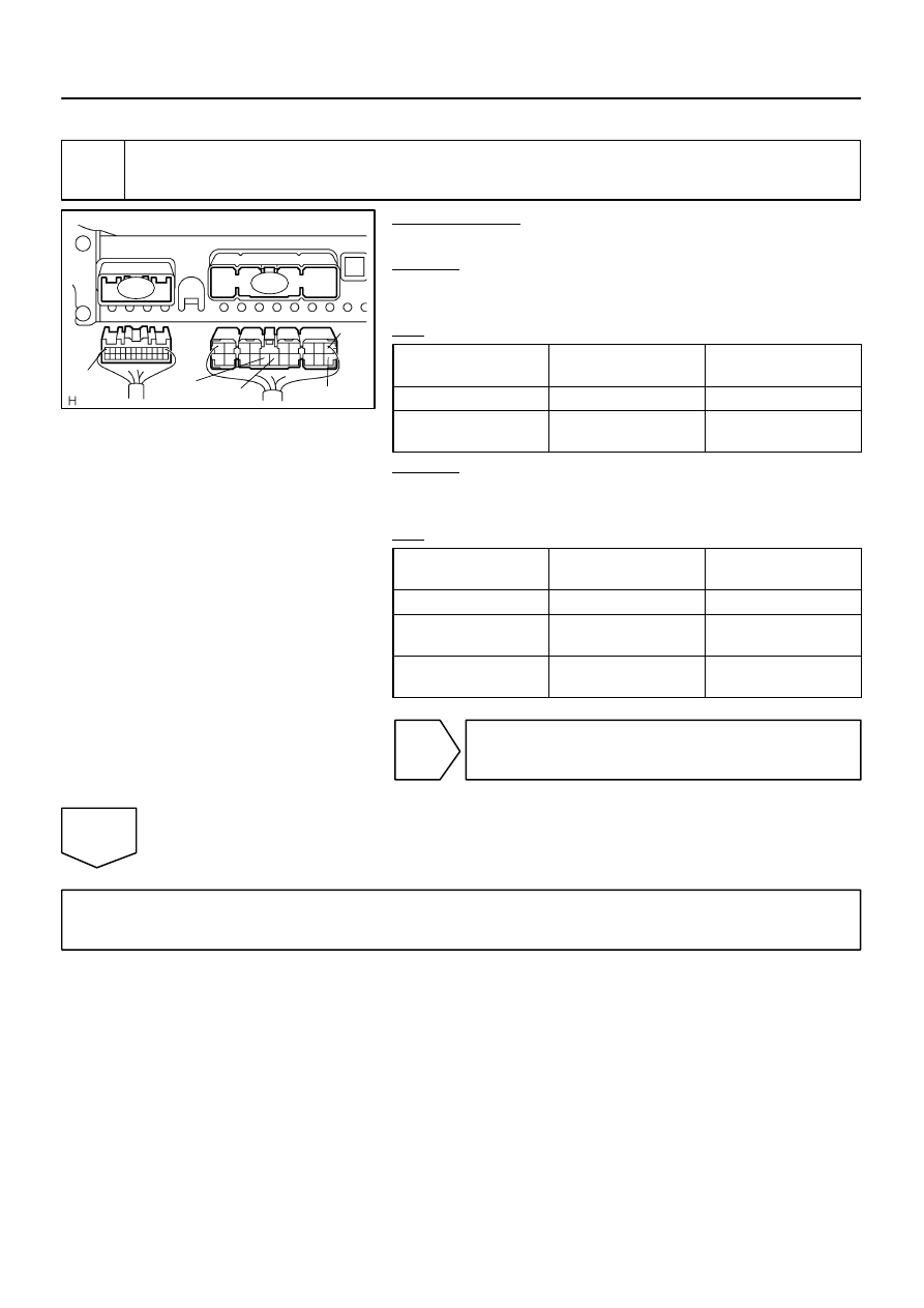
INSPECTION PROCEDURE
1
Inspect stereo component amplifier assy (B+, B2+, ACC, GND, E).
PREPARATION:
Disconnect the stereo component amplifier assy connector.
CHECK:
Measure the resistance according to the value(s) in the table
below.
OK:
Symbol
(Tester connection)
Condition
Specified condition
E (S9–16) – Body ground
Always
Below 1
Ω
GND (S9–15) –
Body ground
Always
Below 1
Ω
CHECK:
Measure the voltage according to the value(s) in the table be-
low.
OK:
Symbol
(Tester connection)
Condition
Specified condition
B+ (S9–1) – GND (S9–15)
Always
10 to 14 V
B2+ (S9–10) –
GND (S9–15)
Always
10 to 14 V
ACC (S10–12) –
GND (S9–15)
Ignition SW ACC
10 to 14 V
NG
Repair or replace harness or connector (Stereo
component amplifier assy – battery or body
ground).
OK
Proceed to next circuit inspection shown in problem symptoms table or diagnostic trouble code
chart (See page
Нет комментариевНе стесняйтесь поделиться с нами вашим ценным мнением.
Текст