Toyota Sequoia (2005). Manual — part 547
–
DIAGNOSTICS
AUDIO SYSTEM
DI–1983
2177
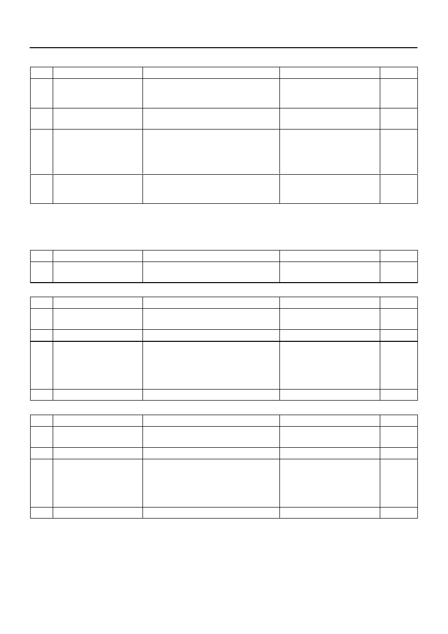
Logical address: 01 (Communication control) continued
DTC
Name
Diagnosis
Verification
See page
E0
*1
Registration Completion
Instruction Error
”Registration Completion Instruction” command
from master cannot be received.
Since this DTC is provided for engi-
neering purposes, it may be de-
tected when no actual failure exists.
–
E2
ON/OFF Instruction Parameter
Error
Error occurs in ON/OFF controlling command
from master component.
Replace radio receiver assy.
–
E3
*1
Registration Request Transmis-
sion
Registration Request command is output from
component shown by sub code.
Receiving Connection Check Instruction, Regis-
tration Request command is output from sub–
master component.
Since this DTC is provided for engi-
neering purposes, it may be de-
tected when no actual failure exists.
–
E4
*1
Multiple Frame Abort
Multiple frame transmission is aborted.
Since this DTC is provided for engi-
neering purposes, it may be de-
tected when no actual failure exists.
–
HINT:
*1: This code may be recorded depending on the battery condition or engine start voltage even if no
failure is detected.
(b)
Logical address: 61 (Cassette switch)
DTC
Name
Diagnosis
Verification
See page
40
Mechanical Error of Media
Malfunction due to mechanical failure is identified.
Either that, or cassette tape is cut or entangled.
1. Inspect cassette tape.
2. Replace radio receiver assy.
–
–
(c)
Logical address: 62 (CD player)
DTC
Name
Diagnosis
Verification
See page
42
No Disc Readout
Disc cannot be read.
1. Inspect CD.
2. Replace radio receiver assy.
–
–
44
CD player Error
Error is detected in CD player.
Replace radio receiver assy.
–
47
Detection of high temperature
High temperature is detected in CD player.
With ignition switch off, leave ve-
hicle in cool shaded place for a
while and recheck. After deleting
the DTC memory, if same code de-
tected, replace radio receiver assy.
–
48
Detection of excess current
Over current is present in CD player.
Replace radio receiver assy.
–
(d)
Logical address: 63 (In–dash CD changer)
DTC
Name
Diagnosis
Verification
See page
42
No Disc Readout
Disc cannot be read.
1. Inspect CD.
2. Replace radio receiver assy.
–
–
44
CD player Error
Error is detected in CDDH.
Replace radio receiver assy.
–
47
Detection of high temperature
High temperature is detected in CDCH.
With ignition switch off, leave ve-
hicle in cool shaded place for a
while and recheck. After deleting
the DTC memory, if same code de-
tected, replace radio receiver assy.
–
48
Detection of excess current
Over current is present in CDCH.
Replace radio receiver assy.
–

DI–1984
–
DIAGNOSTICS
AUDIO SYSTEM
2178
2.
Stereo component amplifier assy (physical address: 440) [DSP–AMP]
Logical address: 01 (Communication control)
DTC
Name
Diagnosis
Verification
See page
D6
*1
Absence of Master
Component in which this code is recorded was
disconnected from system with ignition in ACC or
ON. Either that, or radio receiver assy was dis-
connected when this code was recorded.
1. Power source circuit (Radio re-
ceiver assy).
2. Power source circuit (Stereo
component amplifier assy).
3. AVC–LAN circuit (Radio receiver
assy – Stereo component ampli-
fier assy).
4. AVC–LAN (Radio receiver assy
– Rear seat audio controller). *5
5. AVC–LAN (Radio receiver assy
– Multi–display controller sub–
assy). *6
6. Replace radio receiver assy.
7. Replace stereo component am-
plifier assy.
–
–
D7
Communication Check Error
Component in which this code is recorded is or
was disconnected from system after engine start.
Either that, or radio receiver assy was discon-
nected when this code was recorded.
1. Power source circuit (Radio re-
ceiver assy).
2. Power source circuit (Stereo
component amplifier assy).
3. AVC–LAN circuit (Radio receiver
assy – Stereo component ampli-
fier assy).
4. AVC–LAN (Radio receiver assy
– Rear seat audio controller). *5
5. AVC–LAN (Radio receiver assy
– Multi–display controller sub–
assy). *6
6. Replace radio receiver assy.
7. Replace stereo component am-
plifier assy.
–
–
DC
*2
Transmission Error
Transmission to component shown by auxiliary
code failed.
(Detecting this DTC does not necessarily mean
actual failure.)
If same auxiliary code is recorded in
other components, check harness
for power supply and communica-
tion system of all components
shown by code.
–
DD
*3
Master Reset (Momentary Inter-
ruption)
After engine was started, radio receiver assy was
disconnected from system.
1. Power source circuit (Radio re-
ceiver assy).
2. Power source circuit (Stereo
component amplifier assy).
3. AVC–LAN circuit (Radio receiver
assy – Stereo component ampli-
fier assy).
4. AVC–LAN (Radio receiver assy
– Rear seat audio controller). *5
5. AVC–LAN (Radio receiver assy
– Multi–display controller sub–
assy). *6
6. Replace radio receiver assy.
7. Replace stereo component am-
plifier assy.
–
–

–
DIAGNOSTICS
AUDIO SYSTEM
DI–1985
2179
Logical address: 01 (Communication control) continued
DTC
Name
Diagnosis
Verification
See page
DF
*4
Master Error
Due to defective condition of component with a
display, master function is switched to audio
equipment.
Error occurs in communication between sub–
master (audio) and master component.
1. Power source circuit (Radio re-
ceiver assy).
2. Power source circuit (Stereo
component amplifier assy).
3. AVC–LAN circuit (Radio receiver
assy – Stereo component ampli-
fier assy).
4. AVC–LAN (Radio receiver assy
– Rear seat audio controller). *5
5. AVC–LAN (Radio receiver assy
– Multi–display controller sub–
assy). *6
6. Replace radio receiver assy.
7. Replace stereo component am-
plifier assy.
–
–
E0
*1
Registration Completion
Instruction Error
”Registration Completion Instruction” command
from master cannot be received.
Since this DTC is provided for engi-
neering purposes, it may be de-
tected when no actual failure exists.
–
E1
*1
Audio processor ON error
While source equipment is operating, AMP output
stops.
1. Power source circuit (Radio re-
ceiver assy).
2. Power source circuit (Stereo
component amplifier assy).
3. AVC–LAN circuit (Radio receiver
assy – Stereo component ampli-
fier assy).
4. AVC–LAN (Radio receiver assy
– Rear seat audio controller). *5
5. AVC–LAN (Radio receiver assy
– Multi–display controller sub–
assy). *6
6. Replace radio receiver assy.
7. Replace stereo component am-
plifier assy.
–
–
E2
ON/OFF Instruction Parameter
Error
Error occurs in ON/OFF controlling command
from radio receiver assy.
Replace radio receiver assy.
–
E3
*1
Registration Request Transmis-
sion
Registration Request command is output from
slave component.
Since this DTC is provided for engi-
neering purposes, it may be de-
tected when no actual failure exists.
–
HINT:
*1: This code may be recorded depending on the battery condition or engine start voltage even if no
failure is detected.
*2: This code may be stored if the ignition key is turned to the START position again with the engine
running.
*3: This code may be stored if the ignition key is held in the START position for one minute or more
before returning to the ON position.
*4: If the device is reported as not existing during verification, check the power source circuit and AVC–
LAN circuit for the device.
*5: w/ Rear seat audio system only.
*6: w/ Rear seat entertainment system only.

DI–1986
–
DIAGNOSTICS
AUDIO SYSTEM
2180
3.
Multi–display controller sub–assy (Physical address: 1F6) [RSE ECU, MAIN]
(a)
Logical address: 01 (Communication control)
DTC
Name
Diagnosis
Verification
See page
21
ROM Error
Abnormal condition of ROM is detected.
Replace multi–display controller
sub–assy.
–
22
ROM Error
Abnormal condition of RAM is detected.
Replace multi–display controller
sub–assy.
–
D1
*1
Registered component discon-
nected
AVC–LAN transmitting abnor-
malities
Component shown by sub–code is or was discon-
nected from system with ignition switch in ACC or
ON.
Communication with component shown by sub–
code is not ensured when engine is started.
1. Power source circuit (Multi–dis-
play controller sub–assy).
2. AVC–LAN (Radio receiver assy
– Multi–display controller sub–
assy).
3. Replace Multi–display controller
sub–assy.
–
D7
*2
No response to connection
check
Component shown by sub–code is or was discon-
nected from system after engine started.
1. Power source circuit (Multi–dis-
play controller sub–assy).
2. AVC–LAN (Radio receiver assy
– Multi–display controller sub–
assy).
3. Replace Multi–display controller
sub–assy.
–
D7
*2
AVC–LAN Communication
Check Error
Component in which this code is recorded is or
was disconnected from system after engine start.
Or, when recording this code, multi–display con-
troller was disconnected.
1. Power source circuit (Radio re-
ceiver assy).
2. Power source circuit (Multi–dis-
play controller sub–assy).
3. AVC–LAN (Radio receiver assy
– Multi–display controller sub–
assy).
4. Replace Multi–display controller
sub–assy.
–
D6
*1
Absence of Master
Component in which this code is recorded has
been disconnected from system with ignition in
ACC or ON. Or, when this code was recorded,
multi–display controller was disconnected.
1. Power source circuit (Radio re-
ceiver assy).
2. AVC–LAN (Radio receiver assy
– Multi–display controller sub–
assy).
3. Replace Multi–display controller
sub–assy.
–
D7
*2
Connection Check Error
Component in which this code is recorded has
been disconnected from system after engine start.
Or, when this code was recorded, multi–display
controller was disconnected.
1. Power source circuit (Radio re-
ceiver assy).
2. AVC–LAN (Radio receiver assy
– Multi–display controller sub–
assy).
3. Replace Multi–display controller
sub–assy.
–
DC
*3
Transmission Error
Transmission to component shown by sub–code
has been failed.
(This code does not necessarily mean actual fail-
ure.)
If same sub–code is recorded in
other component(s), check harness
for power supply and communica-
tion system of all components
shown by code.
–
DD
*4
Master Reset (Momentary Inter-
ruption)
Component that is to be master has been discon-
nected after engine start.
1. Power source circuit (Radio re-
ceiver assy).
2. AVC–LAN (Radio receiver assy
– Multi–display controller sub–
assy).
3. Replace Multi–display controller
sub–assy.
–
Нет комментариевНе стесняйтесь поделиться с нами вашим ценным мнением.
Текст