Toyota Sequoia (2005). Manual — part 548

–
DIAGNOSTICS
AUDIO SYSTEM
DI–1987
2181
E0
*1
Registration Completion
Instruction Error
”Registration Completion Instruction” command
from master cannot be received.
Since this DTC is provided for engi-
neering, it may be detected when no
actual failure exists.
–
E3
*1
Registration Request Transmis-
sion
Registration Request command is output from
slave component.
Registration Request command is output from
sub–master component.
Since this DTC is provided for engi-
neering, it may be detected when no
actual failure exists.
–
DF
*4
Master Error
Due to defective condition of component with a
display, master function is switched to audio
equipment.
Error occurs in communication between sub–
master (audio) and master component.
1. Power source circuit (Radio re-
ceiver assy).
2. AVC–LAN (Radio receiver assy
– Multi–display controller sub–
assy).
3. Replace Multi–display controller
sub–assy.
–
E4
*1
Multiple Frame Abort
Multiple frame transmission is aborted.
Since this DTC is provided for engi-
neering purpose, it may be detected
when no actual failure exists.
–
HINT:
*1: Even if no failure is detected, this code may be stored depending on the battery condition or voltage
for starting an engine.
*2: This code is stored when 180 sec. has passed after the power supply connector is pulled out after
engine start.
*3: This code may be stored when the engine key is turned back to the ON position and then turned
again to the START position in 1 minute after engine start.
*4: This code may be stored when the engine key is turned back to the ON position and then turned
again to the START position after engine start.
Rear seat audio controller (Physical address: 1F4) [RSA]
(a)
Logical address: 01 (Communication control)
DTC
Name
Diagnosis
Verification
See page
D6
*1
Absence of Master
Component in which this code is recorded has
been disconnected from system with ignition in
ACC or ON. Or, when this code was recorded,
RSA panel was disconnected.
1. Power source circuit (Radio re-
ceiver assy).
2. AVC–LAN (Radio receiver assy
– Rear seat audio controller).
3. Replace Rear seat audio control-
ler.
–
D7
*2
Connection Check Error
Component in which this code is recorded has
been disconnected from system after engine start.
Or, when this code was recorded, RSA panel was
disconnected.
1. Power source circuit (Radio re-
ceiver assy).
2. AVC–LAN (Radio receiver assy
– Rear seat audio controller).
3. Replace Rear seat audio control-
ler.
–
DC
*3
Transmission Error
Transmission to component shown by sub–code
has been failed.
(This code does not necessarily mean actual fail-
ure.)
If same sub–code is recorded in
other component(s), check harness
for power supply and communica-
tion system of all components
shown by code.
–
DD
*4
Master Reset (Momentary Inter-
ruption)
Component that is to be master has been discon-
nected after engine start.
1. Power source circuit (Radio re-
ceiver assy).
2. AVC–LAN (Radio receiver assy
– Rear seat audio controller).
3. Replace Rear seat audio control-
ler.
–

DI–1988
–
DIAGNOSTICS
AUDIO SYSTEM
2182
E0
*1
Registration Completion
Instruction Error
”Registration Completion Instruction” command
from master cannot be received.
Since this DTC is provided for engi-
neering, it may be detected when no
actual failure exists.
–
E3
*1
Registration Request Transmis-
sion
Registration Request command is output from
slave component.
Registration Request command is output from
sub–master component.
Since this DTC is provided for engi-
neering, it may be detected when no
actual failure exists.
–
DF
*4
Master Error
Due to defective condition of component with a
display, master function is switched to audio
equipment.
Error occurs in communication between sub–
master (audio) and master component.
1. Power source circuit (Radio re-
ceiver assy).
2. AVC–LAN (Radio receiver assy
– Rear seat audio controller).
3. Replace Rear seat audio control-
ler.
–
E4
*1
Multiple Frame Abort
Multiple frame transmission is aborted.
Since this DTC is provided for engi-
neering purpose, it may be detected
when no actual failure exists.
–
D8
*2
No Response To Connection
Check
Component shown by sub–code is or had been
disconnected from system after engine start.
1. Power source circuit (Radio re-
ceiver assy).
2. AVC–LAN (Radio receiver assy
– Rear seat audio controller).
3. Replace Rear seat audio control-
ler.
–
D9
*1
Last Mode Error
Component operated (sound and/or image was
provided) before engine stop is or was discon-
nected with ignition switch in ACC or ON.
1. Power source circuit (Radio re-
ceiver assy).
2. AVC–LAN (Radio receiver assy
– Rear seat audio controller).
3. Replace Rear seat audio control-
ler.
–
DA
No Response to ON/OFF
Instruction
No response is identified when changing mode
(audio and visual mode change).
Detected when sound and picture does not
change by button operation
1. Power source circuit (Radio re-
ceiver assy).
2. AVC–LAN (Radio receiver assy
– Rear seat audio controller).
3. Replace Rear seat audio control-
ler.
–
DB
*1
Mode Status Error
Dual alarm is detected.
1. Power source circuit (Radio re-
ceiver assy).
2. AVC–LAN (Radio receiver assy
– Rear seat audio controller).
3. Replace Rear seat audio control-
ler.
–
DC
*4
Transmission Error
Transmission to component shown by sub–code
has been failed.
(This code does not necessarily mean actual fail-
ure.)
If same sub–code is recorded in
other component(s), check harness
for power supply and communica-
tion system of all components
shown by code.
–
DE
*3
Slave Reset (Momentary Inter-
ruption)
After engine start, slave component has been dis-
connected.
1. Power source circuit (Radio re-
ceiver assy).
2. AVC–LAN (Radio receiver assy
– Rear seat audio controller).
3. Replace Rear seat audio control-
ler.
–
HINT:
*1: Even if no failure is detected, this code may be stored depending on the battery condition or voltage
for starting the engine.
–
DIAGNOSTICS
AUDIO SYSTEM
DI–1989
2183
*2: When 210 sec. has passed after pulling out the power supply connector of the master component
with the ignition switch in ACC or ON, this code is stored.
*3: This code may be stored when the engine key is turned 1 min. again after engine start.
*4: This code may be stored when the engine key is turned again after engine start.
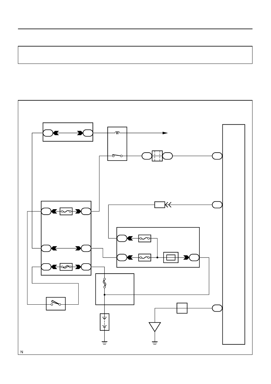
I28499
Built–in Type Amplifier:
Radio Receiver Assy
A36
ACC Cut Relay
Sub J/B No. 3
Instrument Panel J/B
Engine Room J/B
To ECM
Battery
IF
R2
R2
R2
12
3A
1
3A
1
4
3
W–R
2
GR
B
C
B–O
J37
J38
IA1
24
L–Y
L–Y
GR
2B
2C
8
2D
1
RAD No. 1
ECU–B
Short Pin
3
W–R
BR
B
RAD No. 2
3
1
6
AM1
2
12
1
P
3
1
ALT
5
B
I18
Ignition SW
W–L
1
2
A
ACC+B
GND
BU+B
4
3
7
W–R
1J
1E
1L
1C
1C
1F
ACC
AM1
GR
8
F10
Fusible Link Block
4
W
J/C
J12
Junction
Connector
DI–1990
–
DIAGNOSTICS
AUDIO SYSTEM
2184
CIRCUIT INSPECTION
Power source circuit (Radio receiver assy)
CIRCUIT DESCRIPTION
This circuit provides power to the radio receiver assy.
WIRING DIAGRAM
DID9U–01
Нет комментариевНе стесняйтесь поделиться с нами вашим ценным мнением.
Текст