Toyota Sequoia (2005). Manual — part 581
I28667
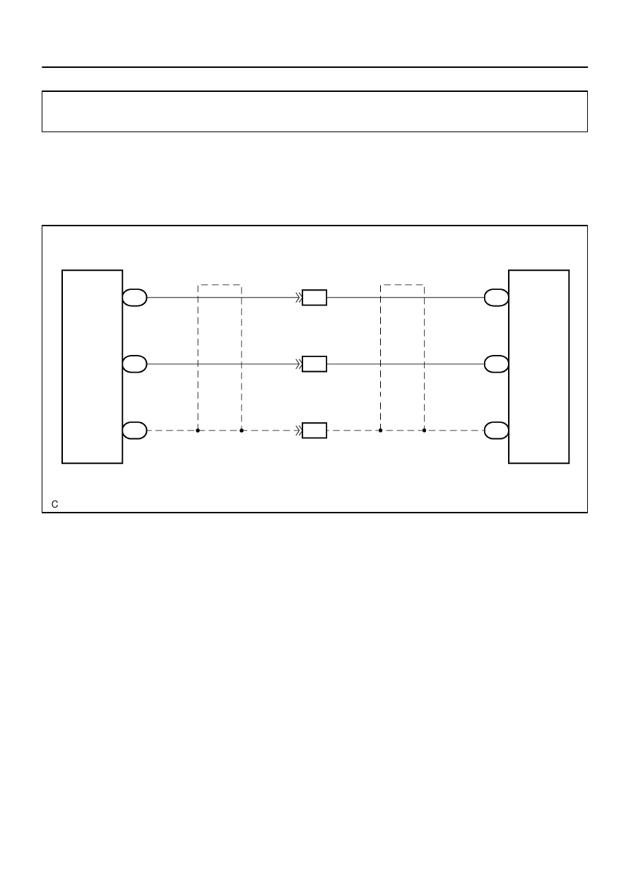
Multi–display
Controller Sub–assy
NTS1
SGN1
SG3
R23
21
R23
20
R23
19
R
G
(Shielded)
Radio and Navigation Assy
BR
BR
(Shielded)
R26
1
R26
4
R26
5
NTSC
SGD1
SGND
IF3
22
IF3
23
IF3
24
–
DIAGNOSTICS
REAR SEAT ENTERTAINMANT SYSTEM
DI–2119
2313
Display signal circuit (Multi–display sub–assy – Radio and navi-
gation assy)
CIRCUIT DESCRIPTION
This is the display signal circuit from the multi–display controller sub–assy to the radio and navigation assy.
WIRING DIAGRAM
DIDB9–01
I28751
NTSC
R26
Radio and Navigation Assy:
SGND
SGD1
I28614
NTS1
R23
Multi–display Controller Sub–assy:
SGN1
SG3
DI–2120
–
DIAGNOSTICS
REAR SEAT ENTERTAINMANT SYSTEM
2314
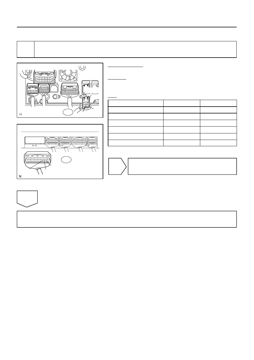
INSPECTION PROCEDURE
1
Check harness and connector (Multi–display controller sub–assy – Radio and
navigation assy).
PREPARATION:
Disconnect the R26 and R23 connectors.
CHECK:
Measure the resistance according to the value(s) in the table
below.
OK:
Symbol (Tester connection)
Condition
Specified condition
NTS1 (R23–21) – NTSC (R26–1)
Always
Below 1
Ω
SGN1 (R23–20) – SGD1 (R26–4)
Always
Below 1
Ω
SG3 (R23–19) – SGND (R26–5)
Always
Below 1
Ω
NTS1 (R23–21) – Body ground
Always
10 k
Ω
or higher
SGN1 (R23–20) – Body ground
Always
10 k
Ω
or higher
SG3 (R23–19) – Body ground
Always
10 k
Ω
or higher
NG
Repair or replace harness or connector.
OK
Proceed to next circuit inspection shown in problem symptoms table (See page
I28666
Multi–display
Controller Sub–assy
NTS4
SGN5
SG6
R21
24
R21
23
R21
22
BR
BR
NTS4
DGND
SGN5
5
6
7
(Shielded)
V10
VTR Terminal
–
DIAGNOSTICS
REAR SEAT ENTERTAINMANT SYSTEM
DI–2121
2315
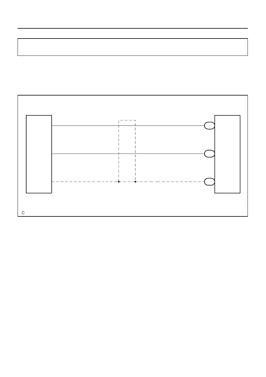
Display signal circuit (Multi–display controller sub–assy – VTR
terminal)
CIRCUIT DESCRIPTION
This is the display signal circuit from the multi–display controller sub–assy to the VTR terminal.
WIRING DIAGRAM
DIDBA–01
I28321
I28327
VTR Terminal:
Multi–display Controller Sub–assy:
NTS4
SGN5
SG6
SGN5
DGND
NTS4
V10
R21
DI–2122
–
DIAGNOSTICS
REAR SEAT ENTERTAINMANT SYSTEM
2316
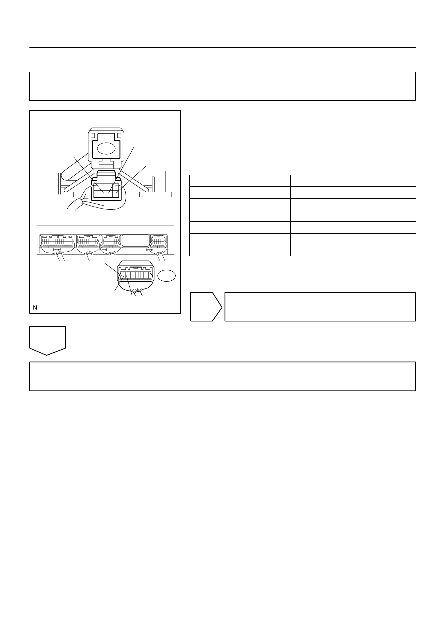
INSPECTION PROCEDURE
1
Check harness and connector (Multi–display controller sub–assy – VTR termi-
nal).
PREPARATION:
Disconnect the V10 and R21 connectors.
CHECK:
Measure the resistance according to the value(s) in the table
below.
OK:
Symbol (Tester connection)
Condition
Specified condition
NTS4 (V10–5) – NTS4 (R21–24)
Always
Below 1
Ω
DGND (V10–6) – SGN5 (R21–23)
Always
Below 1
Ω
SGN5 (V10–7) – SG6 (R21–22)
Always
Below 1
Ω
NTS4 (V10–5) – Body ground
Always
10 k
Ω
or higher
DGND (V10–6) – Body ground
Always
10 k
Ω
or higher
SGN5 (V10–7) – Body ground
Always
10 k
Ω
or higher
NG
Repair or replace harness or connector.
OK
Proceed to next circuit inspection shown in problem symptoms table (See page
Нет комментариевНе стесняйтесь поделиться с нами вашим ценным мнением.
Текст