Toyota Sequoia (2005). Manual — part 128
B17414
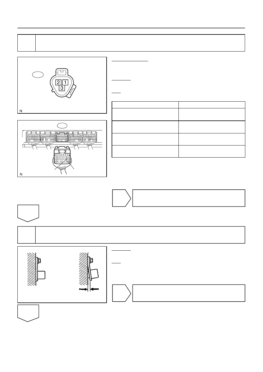
E6
ECM Connector
G2+
G2–
B17445
Wire Harness Side:
Camshaft Position Sensor
C1
BR3795
OK
NG
Clearance
–
DIAGNOSTICS
ENGINE
DI–307
501
3
Check for open and short in harness and connector between ECM and camshaft
position sensor.
PREPARATION:
(a)
Disconnect the Camshaft position sensor connector.
(b)
Disconnect the E6 ECM connector.
CHECK:
Measure the resistance between wire harness side connectors.
OK:
Standard:
Tester Connection
Specified Condition
Camshaft position sensor (C1–2) –
G2+ (E6–19)
Below 1
Ω
Camshaft position sensor (C1–1) –
G2– (E6–29)
Below 1
Ω
Camshaft position sensor (C1–2) or
G2+ (E6–19) – Body ground
10 k
Ω
or higher
Camshaft position sensor (C1–1) or
G2– (E6–29) – Body ground
10 k
Ω
or higher
NG
Repair or replace harness or connector.
OK
4
Inspect sensor installation and signal plate tooth of LH camshaft timing pulley.
CHECK:
Check the camshaft position sensor installation.
OK:
The camshaft position sensor is installed properly.
NG
Tighten sensor installation bolt.
OK

DI–308
–
DIAGNOSTICS
ENGINE
502
5
Inspect signal plate tooth of LH camshaft timing pulley.
NG
Replace LH camshaft timing pulley.
OK
Replace camshaft position sensor.

–
DIAGNOSTICS
ENGINE
DI–309
503
DTC
P1440
Secondary Air Injection System Control
Valve Circuit Bank 1
DTC
P1443
Secondary Air Injection System Control
Valve Circuit Bank 2
CIRCUIT DESCRIPTION
Refer to DTC P0412 on page
.
DTC No.
DTC Detection Condition
Trouble Area
P1440
AIV1 terminal voltage becomes less than half of the +B voltage
while the VSV for air injection control is not operating.
(1 trip detection logic)
Open or short in VSV for air injection control circuit (Bank 1)
VSV power source
VSV for air injection control (Bank 1)
ECM
P1443
AIV2 terminal voltage becomes less than half of the +B voltage
while the VSV for air injection control is not operating.
(1 trip detection logic)
Open or short in VSV for air injection control circuit (Bank 2)
VSV power source
VSV for air injection control (Bank 2)
ECM
MONITOR DESCRIPTION
The ECM detects an open or short in the circuit of the VSV for air injection control according to the AIV1
(AIV2) terminal voltage, stores the DTC, and then illuminates the MIL. When the AIV1 (AIV2) terminal voltage
is less than half of the +B voltage while the VSV for air injection control is not operating, the ECM determines
it as a malfunction.
MONITOR STRATEGY
R l t d DTC
P1440
Secondary air injection system control valve cir-
cuit (Bank 1) range check
Related DTCs
P1443
Secondary air injection system control valve cir-
cuit (Bank 2) range check
Required sensors/components
VSV for air injection control
Frequency of operation
Continuous
Duration
0.5 sec.
MIL operation
Immediate
Sequence of operation
None
DIDMQ–01

DI–310
–
DIAGNOSTICS
ENGINE
504
TYPICAL ENABLING CONDITIONS
It
Specification
Item
Minimum
Maximum
The monitor will run whenever these
DTCs are not present
See page
P1440:
Engine
Running
Air switching valve No. 2 (Bank 1)
Not operating
P1443:
Engine
Running
Air switching valve No. 2 (Bank 2)
Not operating
TYPICAL MALFUNCTION THRESHOLDS
Detection Criteria
Threshold
P1440:
Air switching valve No. 2 (Bank 1) output terminal level
Low
P1443:
Air switching valve No. 2 (Bank 2) output terminal level
Low
Нет комментариевНе стесняйтесь поделиться с нами вашим ценным мнением.
Текст