Toyota Sequoia (2005). Manual — part 129
A23564
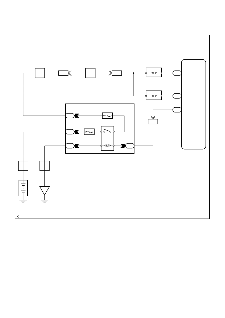
Engine Room J/B
EFI Relay
2
1
EFI No.2
EFI No.1
3
5
2A
2
J5
J/C
A
ED
W–B
1
2F
Battery
B
F10
FL Block
4
5
B
2D
1
2H
6
E4
B–W
IA4
B–W
8
MREL
14
P–L
L–B
E8
E8
27
26
AIV2
AIV1
V14
VSV for Air Injection Control
(Bank 1)
V12
VSV for Air Injection Control
(Bank 2)
G–R
G–R
G–R
G–R
IG4
22
J/C J16
B
B
G–R
IA4
4
G–R
A
A
J/C J2
G–R
ECM
–
DIAGNOSTICS
ENGINE
DI–311
505
WIRING DIAGRAM
B17440
V14
V15
Wire Harness Side:
VSV for Air Injection
Control Connector
B17412
E8
AIV1
AIV2
B17440
V14
V15
Wire Harness Side:
VSV for Air Injection
Control Connector
DI–312
–
DIAGNOSTICS
ENGINE
506
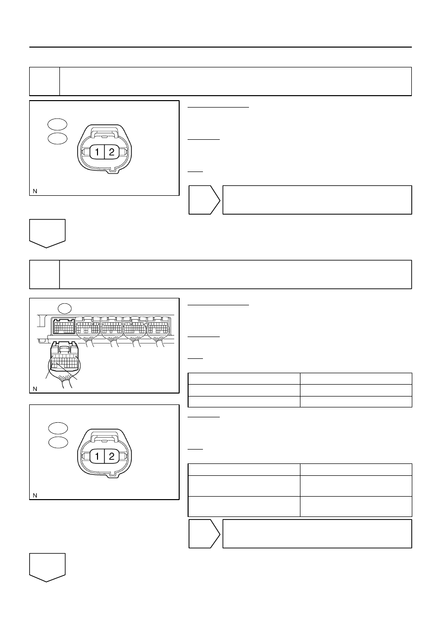
INSPECTION PROCEDURE
1
Check VSV for air injection control power source.
PREPARATION:
(a)
Disconnect the VSV for air injection control connector.
(b)
Turn the ignition switch ON.
CHECK:
Measure the voltage between the terminal 1 of the VSV con-
nector and body ground.
OK:
Standard: 9 V or more
NG
Check and replace harness and connector.
OK
2
Check for open and short circuit in harness and connector between ECM and
VSV for air injection control
PREPARATION:
(a)
Disconnect the E8 ECM connector.
(b)
Disconnect the VSV for air injection control connector.
CHECK:
Measure the resistance between the VSV connector and ECM.
OK:
Standard:
Tester connection
Specified condition
E8–27 (AIV1) – V14–2
Below 1
Ω
E8–26 (AIV2) – V15–2
Below 1
Ω
CHECK:
Measure the resistance between the VSV connector and body
ground.
OK:
Standard:
Tester connection
Specified condition
E8–27 (AIV1) or V14–2 and Body
ground
10 K
Ω
or higher
E8–26 (AIV1) or V15–2 and Body
ground
10 K
Ω
or higher
NG
Repair or replace harness or connector.
OK
B17515
–
DIAGNOSTICS
ENGINE
DI–313
507
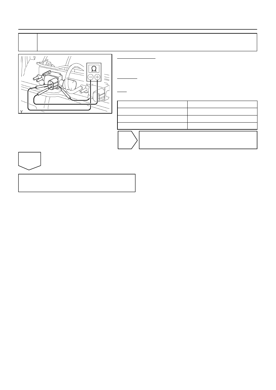
3
Check resistance of VSV for air injection control.
PREPARATION:
(a)
Disconnect the connector from the VSV.
(b)
Disconnect the 2 vacuum hoses from the VSV.
CHECK:
Measure the resistance between the VSV terminals.
OK:
Standard:
Tester Connection
Specified Condition
1 – 2
33 to 39
Ω
at 20
°
C (68
°
F)
1 – Body ground
10 k
Ω
or higher
2 – Body ground
10 k
Ω
or higher
NG
Replace VSV for air injection control.
OK
DI–314
–
DIAGNOSTICS
ENGINE
508
DTC
P1441
Secondary Air Injection System Switching
Valve No.2 Stuck Open Bank 1
DTC
P1444
Secondary Air Injection System Switching
Valve No.2 Stuck Open Bank 2
DTC
P2440
Secondary Air Injection System Switching
Valve Stuck Open Bank 1
CIRCUIT DESCRIPTION
Refer to DTC P0412 on page
.
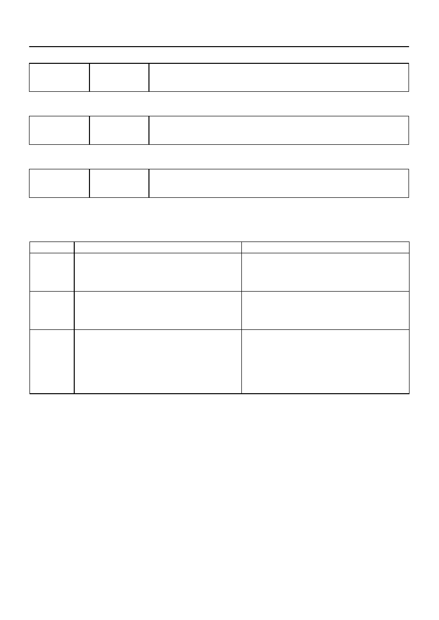
DTC No.
DTC Detection Condition
Trouble Area
P1441
Air switching valve No.2 (bank 1) stuck open:
The pressure sensor detects exhaust pulsation, when both of
air switching valve No.2 are OFF (and air switching valve ON).
(2 trip detection logic)
VSV for air injection control circuit (Bank 1)
Air switching valve No.2 (Bank 1)
VSV for air injection system (Bank 1)
ECM
P1444
Air switching valve No.2 (bank 2) stuck open:
The pressure sensor detects exhaust pulsation, when both of
air switching valve No.2 are OFF (and air switching valve ON).
(2 trip detection logic)
VSV for air injection control circuit (Bank 2)
Air switching valve No.2 (Bank 2)
VSV for air injection system (Bank 2)
ECM
P2440
Air switching valve stuck open:
The pressure sensor detects exhaust pulsation when the sys-
tem does not operate (both of air switching valve No.2 OFF,
and air switching valve OFF and air pump OFF).
This DTC means open stuck of air switching valve and ”air
switching valve No.2 (bank 1 or bank 2)”
(1 trip detection logic)
Air switching valve
Air switching valve No.2 (Bank 1 and/or 2)
VSV for air injection system (Bank 1 and/or 2)
Air injection driver
Air injection driver circuit
ECM
DIDMR–01
Нет комментариевНе стесняйтесь поделиться с нами вашим ценным мнением.
Текст