Toyota Sequoia (2005). Manual — part 127

–
DIAGNOSTICS
ENGINE
DI–303
497
INSPECTION PROCEDURE
1
Read current DTC.
NOTICE:
If P0630 is present, the VIN must be input to the ECM using the hand–held tester. However, all DTCs
are cleared automatically by the tester when inputting the VIN. If DTCs other than P0630 are present,
check them first.
NEXT
2
Input VIN with hand–held tester (See page
NEXT
END

DI–304
–
DIAGNOSTICS
ENGINE
498
DTC
P1340, P1341
Camshaft Position Sensor ”A” (Bank
Sensor 1)
CIRCUIT DESCRIPTION
Camshaft position sensor (G signal) consists of a magnet, iron core and pickup coil.
The camshaft drive gear (LH) has 3 teeth on its inner circumference. When the camshaft gear rotates, air
gap changes between the protrusion on the gear and the pickup coil. The change affects the magnetic field
and result in change in the resistance of the MRE element.
The crankshaft signal plate has 32 teeth and is mounted on the crankshaft. The crankshaft position sensor
generates 32 signals at every engine revolution. The ECM detects the standard crankshaft angle based on
the G signal and the actual crankshaft angle and the engine speed by the NE signal.
DTC No.
DTC Detecting Condition
Trouble Area
P1340
No camshaft position sensor signal to ECM during cranking
(2 trip detection logic)
Open or short in camshaft position sensor circuit
Camshaft position sensor
P1340
P1341
No camshaft position sensor signal to ECM with engine speed
600 rpm or more
Camshaft osition sensor
LH camshaft timing pulley
ECM
MONITOR DESCRIPTION
The camshaft position sensor (G signal) consists of a magnet and MRE element.
The camshaft drive gear has 5 teeth on its inner circumference. When the camshaft gear rotates, air gap
changes between the protrusion on the gear and the pickup coil. The change affects the magnetic field and
result in change in the resistance of the MRE element. The crankshaft angle sensor plate has 32 teeth and
output 32 signals every engine revolution. The ECM detects the standard crankshaft angle based on the
G signal and actual crankshaft angle and engine speed by NE signal.
MONITOR STRATEGY
R l t d DTC
P1340
Camshaft position sensor (Bank 1) range check
or rationality
Related DTCs
P1341
Camshaft position sensor (Bank 1) range check
or rationality
R
i d
/
t
Main sensors/components
Camshaft position sensor
Required sensors/components
Related sensors/components
Crankshaft position sensor, Engine speed sensor
Frequency of operation
Continuous
Duration
5 sec.
MIL operation
P1340 case 1 (no signal): 2 driving cycles
P1340 case 2 (mis–aligned), P1341: Immediate
Sequence of operation
None
TYPICAL ENABLING CONDITIONS
It
Specification
Item
Minimum
Maximum
The monitor will run whenever these
DTCs are not present
See page
P1340 Case 1 (No signal):
Starter
ON
Minimum battery voltage while starter ON
–
11 V
DID8F–01
A23558
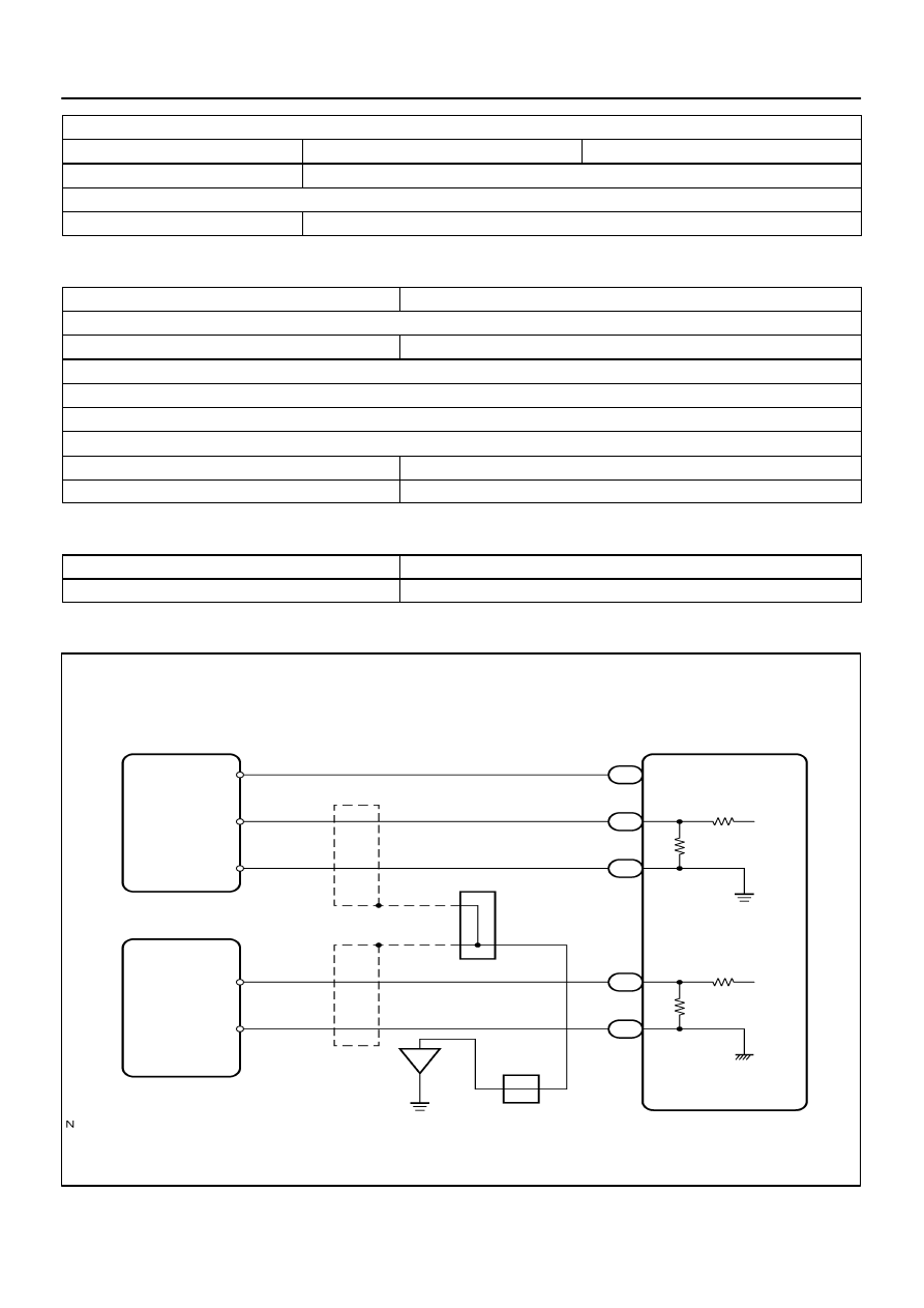
C2
Crankshaft Position Sensor
*1: Shielded
C1
Crankshaft Position Sensor
ECM
G–B
(*1)
(*1)
VC
E2
EC
BR
J42
J/C
D
D
BR
2
Y
1
2
L
G
R
G2+
G2–
NE+
NE–
1
23
E8
19
E6
29
E6
21
E6
20
E6
E
E
E
J42 J/C
–
DIAGNOSTICS
ENGINE
DI–305
499
P1340 Case 2 (Mis–aligned):
Engine RPM
600 rpm
–
Starter
OFF
P1341:
Starter
After OFF to ON timing
TYPICAL MALFUNCTION THRESHOLDS
Detection Criteria
Threshold
P1340 Case 1 (No signal):
Camshaft position sensor signal
No signal
P1340 Case 2 (Mis–aligned):
Crankshaft/camshaft alignment is mis–aligned (judged by comparing the crankshaft position to the camshaft position)
Camshaft position sensor signal: No input in appropriate timing.
P1341:
Crankshaft/Camshaft alignment
Mis–aligned
Camshaft position sensor count
12 or more / 720
CA (= Engine 2 revolutions)
COMPONENT OPERATING RANGE
Parameter
Standard Value
Camshaft position sensor signal input at every 720
CA
3
WIRING DIAGRAM
B17445
Wire Harness Side:
Camshaft Position Sensor
A23559
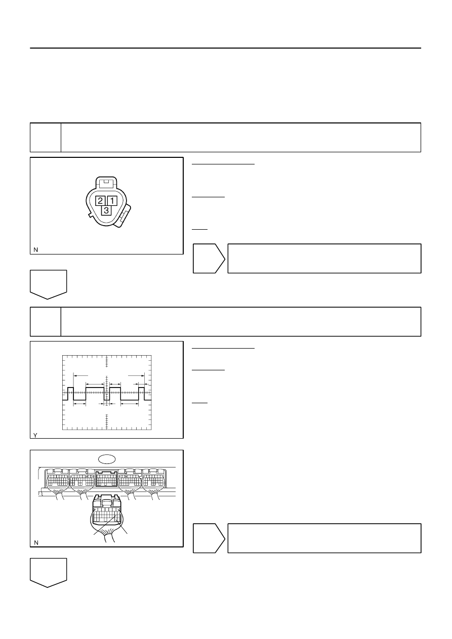
2 V / DIV
GND
Crank Angle
120
°
120
°
180
°
180
°
60
°
60
°
200 ms /DIV
B17414
E6
ECM Connector
G2+
G2–
DI–306
–
DIAGNOSTICS
ENGINE
500
INSPECTION PROCEDURE
HINT:
Read freeze frame data using hand–held tester. Because freeze frame records the engine conditions when
the malfunction is detected. When troubleshooting, it is useful for determining whether the vehicle was run-
ning or stopped, the engine was warmed up or not, the air–fuel ratio was lean or rich, etc. at the time of the
malfunction.
1
Check voltage of camshaft position sensor power source circuit.
PREPARATION:
(a)
Disconnect the Camshaft position sensor connector.
(b)
Turn the ignition switch to ON.
CHECK:
Measure the voltage between terminal 3 of the camshaft posi-
tion sensor connector and body ground.
OK:
Standard: 4.5 to 5.5 V
NG
Repair or replace harness or connector.
OK
2
Check camshaft position sensor signal.
PREPARATION:
Start the engine.
CHECK:
Check the waveform between the G2+ (E6–19) and G2–
(E6–29) of the ECM connector.
OK:
Standard: Correct waveform is as shown.
OK
Replace ECM (See page
NG
Нет комментариевНе стесняйтесь поделиться с нами вашим ценным мнением.
Текст