Toyota Sequoia (2005). Manual — part 149

–
DIAGNOSTICS
ENGINE
DI–391
585
INSPECTION PROCEDURE
HINT:
Malfunctioning areas can be identified by performing the A/F CONTROL function provided in the ACTIVE
TEST. The A/F CONTROL function can help to determine whether the Air–Fuel Ratio (A/F) sensor, Heated
Oxygen (HO2) sensor and other potential trouble areas are malfunctioning.
The following instructions describe how to conduct the A/F CONTROL operation using a hand–held tester.
(1)
Connect a hand–held tester to the DLC3.
(2)
Start the engine and turn the tester ON.
(3)
Warm up the engine at an engine speed of 2,500 rpm for approximately 90 seconds.
(4)
On the tester, select the following menu items: DIAGNOSIS / ENHANCED OBD II / ACTIVE
TEST / A/F CONTROL.
(5)
Perform the A/F CONTROL operation with the engine in an idling condition (press the RIGHT
or LEFT button to change the fuel injection volume).
(6)
Monitor the voltage outputs of the A/F and HO2 sensors (AFS B1S1 (AFS B2S1) and OS2 B1S2
(O2S B2S2)) displayed on the tester.
HINT:
The A/F CONTROL operation lowers the fuel injection volume by 12.5 % or increases the injection
volume by 25 %.
Each sensor reacts in accordance with increases and decreases in the fuel injection volume.
Standard:
Tester Display
(Sensor)
Injection Volumes
Status
Voltages
AFS B1S1 (AFS B2S1)
(A/F)
+25 %
Rich
Less than 3.0
AFS B1S1 (AFS B2S1)
(A/F)
–12.5 %
Lean
More than 3.35
O2S B1S2 (O2S B2S2)
(HO2)
+25 %
Rich
More than 0.55
O2S B1S2 (O2S B2S2)
(HO2)
–12.5 %
Lean
Less than 0.4
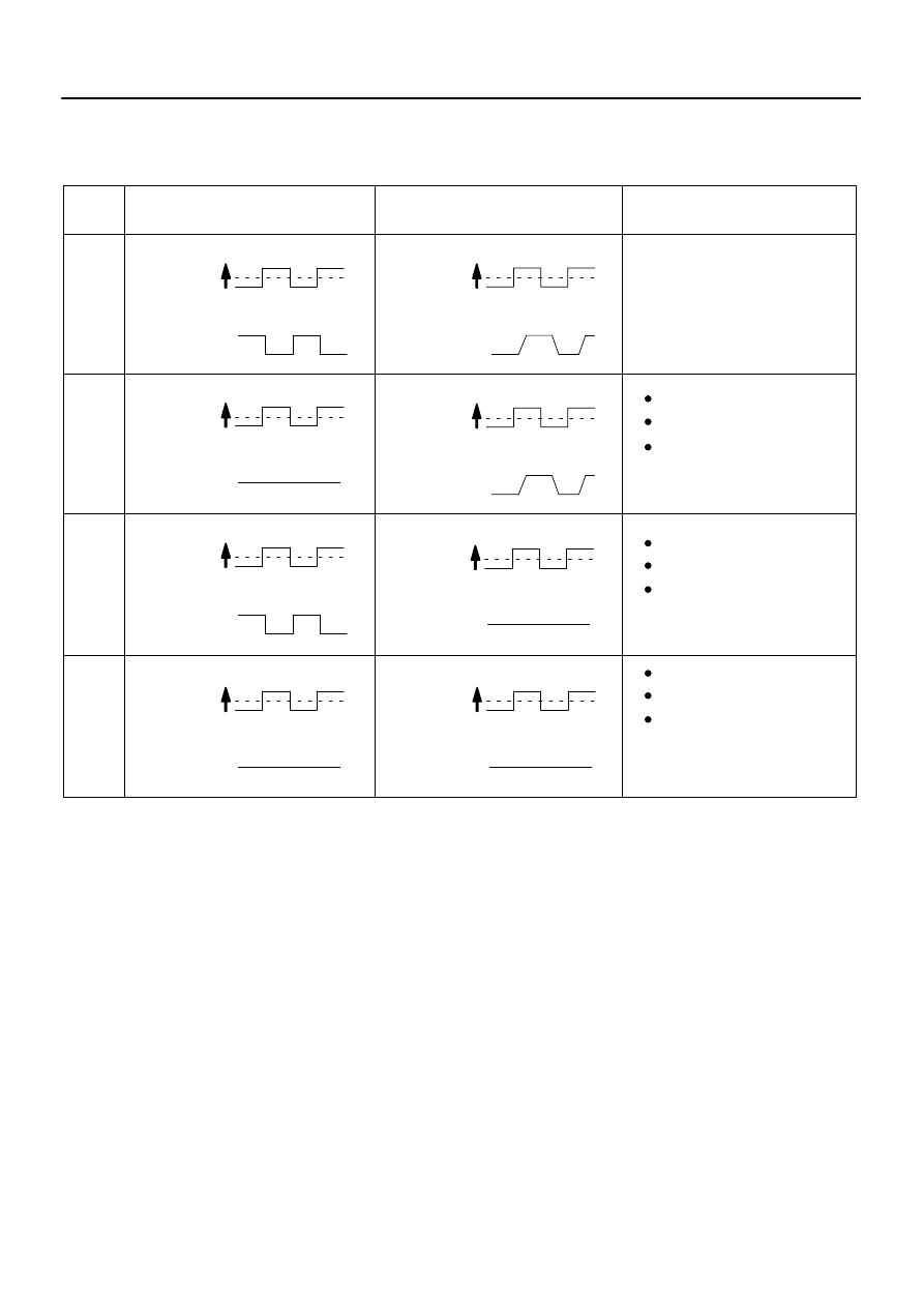
+25 %
–12.5 %
More than 3.35 V
Less than 3.0 V
1
A/F Sensor (Sensor 1)
Output Voltage
Injection volume
Output voltage
HO2 Sensor (Sensor 2)
Output Voltage
Main Suspected
Trouble Areas
OK
+25 %
–12.5 %
More than 3.35 V
Less than 3.0V
Injection volume
Output voltage
+25 %
–12.5 %
More than 0.55 V
Less than 0.4V
Injection volume
Output voltage
A/F sensor
+25 %
–12.5 %
More than 0.55 V
Less than 0.4V
Injection volume
Output voltage
+25 %
–12.5 %
Injection volume
Output voltage
NG
+25 %
–12.5 %
Injection volume
Output voltage
NG
+25 %
–12.5 %
Injection volume
Output voltage
NG
+25 %
–12.5 %
Injection volume
Output voltage
NG
OK
OK
OK
Almost
no reaction
Almost
no reaction
Almost
no reaction
Almost
no reaction
Case
2
3
4
A/F sensor circuit
A/F sensor heater
HO2 sensor
HO2 sensor circuit
HO2 sensor heater
(Air–fuel ratio extremely
lean or rich)
Injector
Gas leakage from
exhaust system
Fuel pressure
DI–392
–
DIAGNOSTICS
ENGINE
586
NOTICE:
The Air–Fuel Ratio (A/F) sensor has an output delay of a few seconds and the Heated Oxygen (HO2)
sensor has a maximum output delay of approximately 20 seconds.
Following the A/F CONTROL procedure enables technicians to check and graph the voltage outputs
of both the A/F and HO2 sensors.
To display the graph, select the following menu items on the tester: DIAGNOSIS / ENHANCED OBD
II / ACTIVE TEST / A/F CONTROL / USER DATA / AFS B1S1 and O2S B1S2, and press the YES but-
ton and then the ENTER button followed by the F4 button.
HINT:
Read freeze frame data using a hand–held tester. Freeze frame data record the engine condition when
malfunctions are detected. When troubleshooting, freeze frame data can help determine if the vehicle
was moving or stationary, if the engine was warmed up or not, if the air–fuel ratio was lean or rich, and
other data, from the time the malfunction occurred.
A low A/F sensor voltage could be caused by a rich air–fuel mixture. Check for conditions that would
cause the engine to run rich.
A high A/F sensor voltage could be caused by a lean air–fuel mixture. Check for conditions that would
cause the engine to run lean.
–
DIAGNOSTICS
ENGINE
DI–393
587
1
Check any other DTCs output (in addition to DTC P2195, P2196, P2197 or P2198).
PREPARATION:
(a)
Connect a hand–held tester to the DLC3.
(b)
Turn the ignition switch to ON and turn the tester ON.
(c)
Select the following menu items: DIAGNOSIS / ENHANCED OBD II / DTC INFO / CURRENT CODES.
CHECK:
(a)
Read DTCs.
Result:
Display (DTC Output)
Proceed To
P2195, P2196, P2197 or P2198
A
P2195, P2196, P2197 or P2198 and other DTCs
B
HINT:
If any DTCs other than P2195, P2196, P2197 or P2198 are output, troubleshoot those DTCs first.
B
).
A
2
Check A/F sensor output current.
PREPARATION:
(a)
Connect a hand–held tester to the DLC3.
(b)
Turn the ignition switch to ON and turn the tester ON.
(c)
Clear DTCs (see page
(d)
On the hand–held tester, select the following menu items: DIAGNOSIS/ENHANCED OBD II/MON-
ITOR INFO/MONITOR STATUS.
(e)
Check that the status of O2S MON is COMPL.
(f)
On the hand–held tester, select the following menu items: DIAGNOSIS/ENHANCED OBD II/MON-
ITOR INFO/TEST RESULT/RANGE BISI and B2S1.
(g)
Check the test value of the air–fuel ratio sensor output current during fuel–cut.
RESULT:
Test Value
Proceed to
Out of normal range (1.4 mA or more, and less than 3.6 mA)
A
Within normal range (Less than 1.4 mA, or 3.6 mA or more)
B
B
Go to step 20.
A
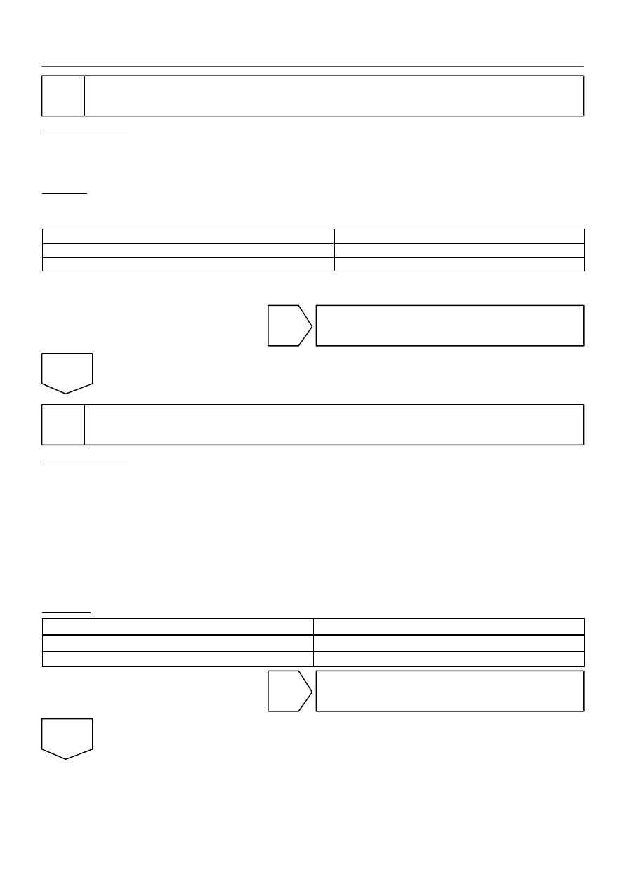
B17393
Engine
RPM
Engine
RPM
(1) Idling
(2) Approximately 2,500 rpm
Fuel Cut
When A/F sensor circuit malfunctioning,
voltage output does not change
A/F
Sensor
Voltage
A/F
Sensor
Voltage
(1) Idling
Fuel Cut
(3) Approximately 4,000 rpm
”Condition (1), (2)”
Change at approximately 0.66 V
Normal Condition:
Malfunction Condition:
”Condition (3)”
0.76 V or More
(1) Idling
(2) Approximately 2,500 rpm
(3) Approximately 4,000 rpm
(1) Idling
DI–394
–
DIAGNOSTICS
ENGINE
588
3
Read value output voltage of A/F sensor.
PREPARATION:
(a)
Connect the hand–held tester to the DLC3.
(b)
Start the engine and turn the scan tool ON.
(c)
Warm up the Air–Fuel Ratio (A/F) sensor at an engine speed of 2,500 rpm for 90 seconds.
CHECK:
(a)
Using the scan tool, check the A/F sensor voltage 3 times, once when the engine is in each of the fol-
lowing conditions:
(1)
While idling (check for at least 30 seconds)
(2)
At an engine speed of approximately 2,500 rpm (without any sudden changes in engine speed)
(3)
Raise the engine speed to 4,000 rpm and then quickly release the accelerator pedal so that the
throttle valve is fully closed.
Standard:
Conditions
A/F Sensor Voltage Variations
Reference
(1) and (2)
Changes at approx 0.66 V
Between 0.62 V and 0.7 V
(3)
Increases to 0.76 V or more
This occurs during engine deceleration
(when fuel–cut performed)
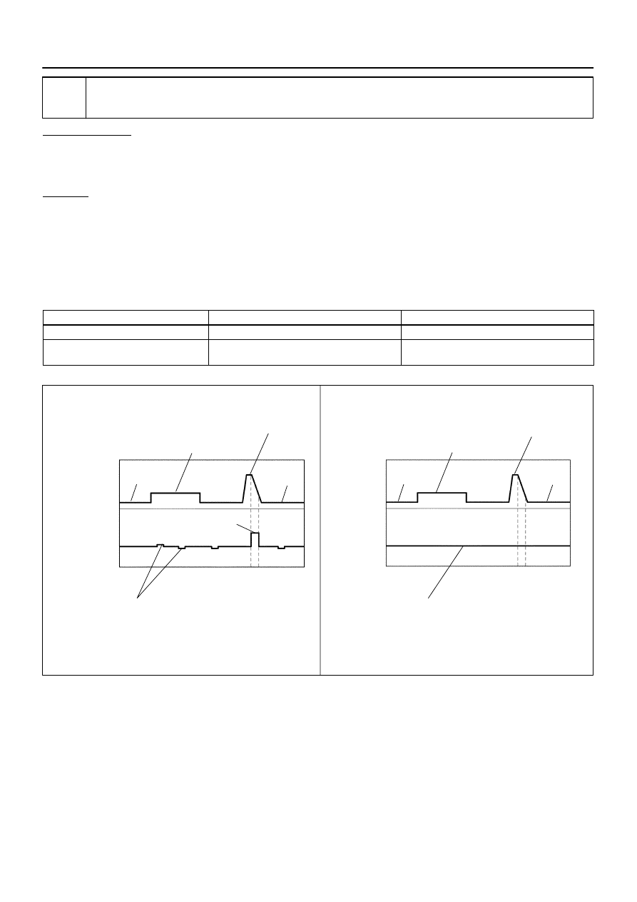
For more information, see the diagrams below.
HINT:
If the output voltage of the A/F sensor remains at approximately 0.66 V (see Malfunction Condition
diagram) under any conditions, including those above, the A/F sensor may have an open circuit. (This
will also happen if the A/F sensor heater has an open circuit.)
If the output voltage of the A/F sensor remains at either approximately 0.76 V or more, or 0.56 V or
less (see Malfunction Condition diagram) under any conditions, including those above, the A/F sensor
may have a short circuit.
The ECM stops fuel injection (fuel cut) during engine deceleration. This causes a lean condition and
results in a momentary increase in the A/F sensor output voltage.
Нет комментариевНе стесняйтесь поделиться с нами вашим ценным мнением.
Текст